
Modular Thermal Management System for Spacecraft

a module-based, spacecraft-based technology, applied in the field of heat transfer, can solve the problems of spacecraft launch load, spacecraft one particular demanding environment, and spacecraft requiring cooling, so as to reduce the requirement for heat rejection, increase the solar load reduction, and increase the time on target

Inactive Publication Date: 2008-11-27
UTAH STATE UNIVERSITY
View PDF32 Cites 18 Cited by
  • Summary
  • Abstract
  • Description
  • Claims
  • Application Information

AI Technical Summary

Benefits of technology

The present invention is a modular, dual-function, structural-thermal-integrated spacecraft system that integrates thermal management and structural requirements for satellite and other spacecraft systems. The system includes flexible thermal links, pivoting thermal links, and doors that function as both reflective surfaces and emissive panels. The panels have high emissivity finishes and can operate independently. The system allows for efficient heat transfer and stable temperature control, with temperature differences between panels ranging from tens to hundreds of degrees. The panels can be thermally connected or left to function independently. The system also provides a means for controlling the radiation of heat from the panels and augmenting it for better performance. The panels can be used to cover the entire surface of a spacecraft or just a portion of it. The system has a high level of thermal contact between the panels, which allows for effective heat transfer and minimal temperature differentials. The panels can be exposed to solar radiation or shaded, and the system can be designed to provide efficient radiation and solar electric device augmentation. The system provides a flexible and effective solution for managing heat and radiation in spacecraft systems.

Problems solved by technology

Meanwhile, electrical and electronic devices that consume electricity likewise require cooling.
One particularly demanding environment occurs with spacecraft.
Meanwhile, the loads required of any structure during launch may be substantial.
Thus, the combination of light weight and high strength is difficult to achieve.
By contrast, composite materials such as bonded composites, fiber-reinforced layers, and the like typically have comparatively poor thermal conductivity.

Method used


Image

  • Modular Thermal Management System for Spacecraft
  • Modular Thermal Management System for Spacecraft
  • Modular Thermal Management System for Spacecraft

Examples


Embodiment Construction

[0046]It will be readily understood that the components of the present invention, as generally described and illustrated in the drawings herein, could be arranged and designed in a wide variety of different configurations. Thus, the following more detailed description of the embodiments of the system and method of the present invention, as represented in the drawings, is not intended to limit the scope of the invention, as claimed, but is merely representative of various embodiments of the invention. The illustrated embodiments of the invention will be best understood by reference to the drawings, wherein like parts are designated by like numerals throughout.

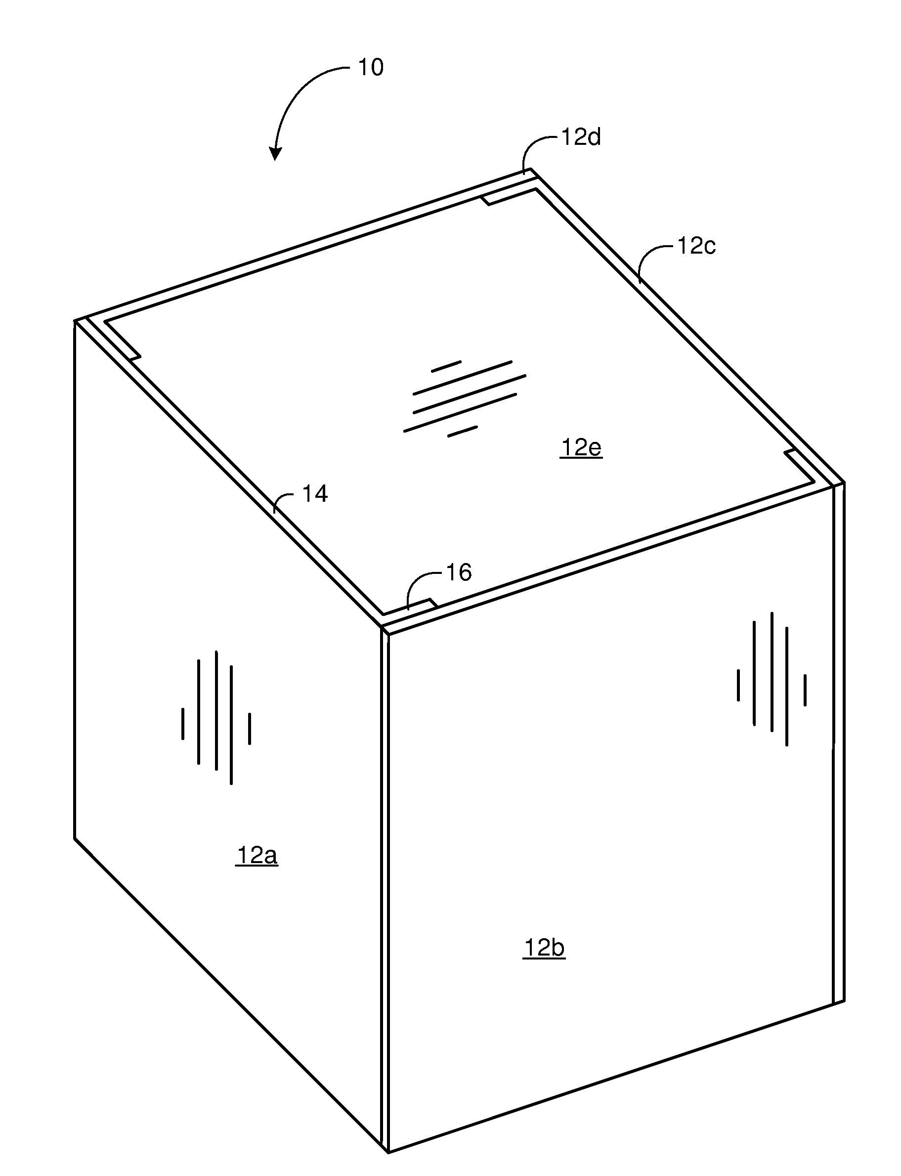
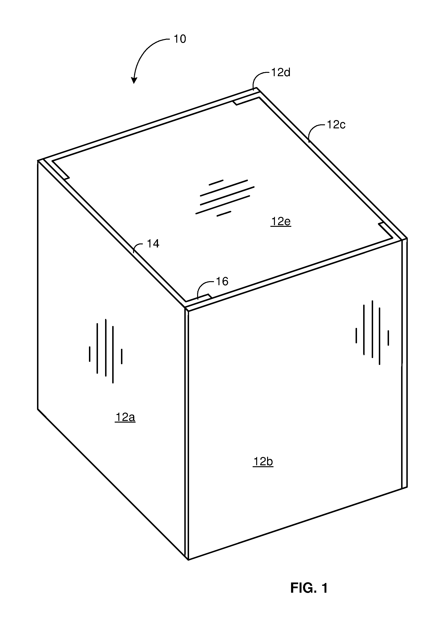
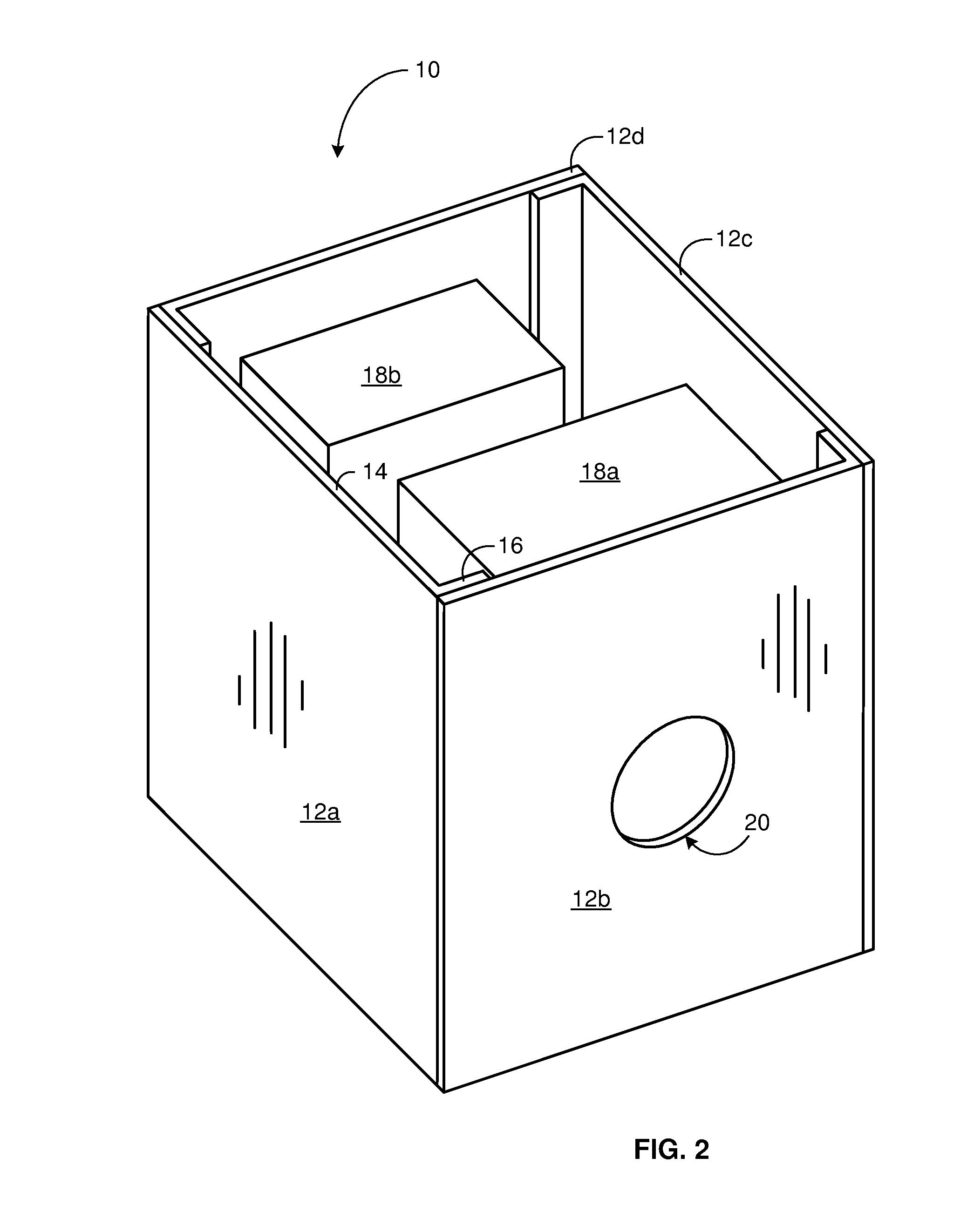
[0047]Referring to FIG. 1, and to FIGS. 1-13 generally, a system 10 in accordance with the invention may include various panels 12 providing dual-service, structural-thermal, integrated, modular panels 12. These panels are disclosed in detail in various selected embodiments in the documents, incorporated herein by reference.

[004...


PUM


Abstract

A composite panel provides structural strength and rigidity for modular assembly of spacecraft while serving the dual purposes of structure and heat transfer for thermal management of an environment for equipment, such as a spacecraft. Instruments, gimbals, surveillance, imaging, detectors, and the like may be mounted in a spacecraft designed and constructed from standard panels to provide the structural and heat transfer requirements to support the onboard equipment. Extremely small temperature differentials required by the panels support a substantially isothermal perimeter for the structure, able to sink heat from any location on a panel, transport it to a rejection site, and reject it to the cold environment of space, thus easing the task of design and packaging of instrumentation and infrastructure of satellites and other spacecraft. Two-phase mass transport of fluids inside the panels aids high heat flux rates with minimal temperature differentials, even with reinforced, composite, polymeric materials for the structural elements of the panels.

Description

RELATED APPLICATIONS[0001]This application: (1) is a continuation-in-part of co-pending U.S. patent application Ser. No. 11 / 743,555, filed on May 2, 2007; (2) claims the benefit of co-pending U.S. Provisional Patent Application Ser. No. 60 / 954,550, filed on Aug. 7, 2007; and (3) claims the benefit of co-pending U.S. Provisional Patent Application Ser. No. 61 / 042,205, filed on Apr. 3, 2008.BACKGROUND[0002]1. The Field of the Invention[0003]This invention relates to heat transfer and, more particularly, to novel systems and methods for combined structural and heat transfer panels for spacecraft.[0004]2. The Background Art[0005]Heat transfer is fundamental to many processes. Engines releasing energy from fuel must routinely reject heat. Meanwhile, electrical and electronic devices that consume electricity likewise require cooling. One particularly demanding environment occurs with spacecraft. Spacecraft contain many electronic instruments. Weight is at a premium, as is space. Meanwhile...

Claims


Application Information

Patent Timeline
Patent Type & Authority Applications(United States)
IPC IPC(8): F28D15/00
CPCB64G1/44B64G1/503B64G1/506F28D15/02
Inventor BATTY, J. CLAIRJENSEN, SCOTT M.
Owner UTAH STATE UNIVERSITY
Learn More