Method of Manufacturing Sample for Atom Probe Analysis by FIB and Focused Ion Beam Apparatus Implementing the Same

a technology of atom probe and focused ion beam, which is applied in the direction of scanning probe techniques, instruments, vacuum evaporation coating, etc., can solve the problems of difficult to analyze a fine specified site by the ap, transplantation piece in the front from the joint part flies and is lost, and achieves the effect of easy implementation of the transplanting/bonding method

Inactive Publication Date: 2008-11-27
HITACHI HIGH TECH SCI CORP
View PDF1 Cites 9 Cited by
  • Summary
  • Abstract
  • Description
  • Claims
  • Application Information

AI Technical Summary

Benefits of technology

[0015]Since the focused ion beam apparatus of the invention, which implements the method of manufacturing the sample for the atom probe analysis, is made one in which the member retaining the base needle additionally possesses, on the stage having the electric motored five-axis, the function capable of rotating about the needle axis and the function capable of switching the slant at least between 0° and 90°, by using freely the rotation function and the slant function it is possible to easily implement a transplanting / bonding method of the atom probe sample piece of the invention. Further, since there is adopted a form in which the member retaining the base needle is installed on the stage having the electric motored five-axis, there can be easily provided only by performing a working for attaching the retention member to an existing FIB apparatus.

Problems solved by technology

However, for this AP, there is a strict restriction in a manufacture and a shape of a sample, so that a field in which its characteristic can be practically used is limited.
In order to analyze the analysis object like this by using the AP, although it is necessary to locally cut out a place desired to be analyzed and fix it to a tip of a needle-like protrusion becoming an electrode while being cut out as a fine section, hitherto there merely exists only a conventional method of making a sample of metal material or the like into needle-like one, so that it is very difficult to analyze a fine specified site by the AP.
However, in this sample piece picking / transplanting technique, there is the fact that there generates such an issue that, by a strong electrostatic attraction force at an AP analysis time, a transplantation piece in a front from a joint part flies and is lost.
This issue is one generating because a strength of an interface between a deposition film and a material to be bonded, which are bonded by the FIB-CVD, is insufficient and they are exfoliated.

Method used


Image

  • Method of Manufacturing Sample for Atom Probe Analysis by FIB and Focused Ion Beam Apparatus Implementing the Same
  • Method of Manufacturing Sample for Atom Probe Analysis by FIB and Focused Ion Beam Apparatus Implementing the Same
  • Method of Manufacturing Sample for Atom Probe Analysis by FIB and Focused Ion Beam Apparatus Implementing the Same

Examples


embodiment 1

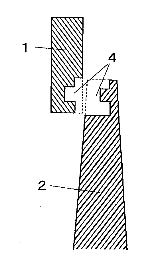
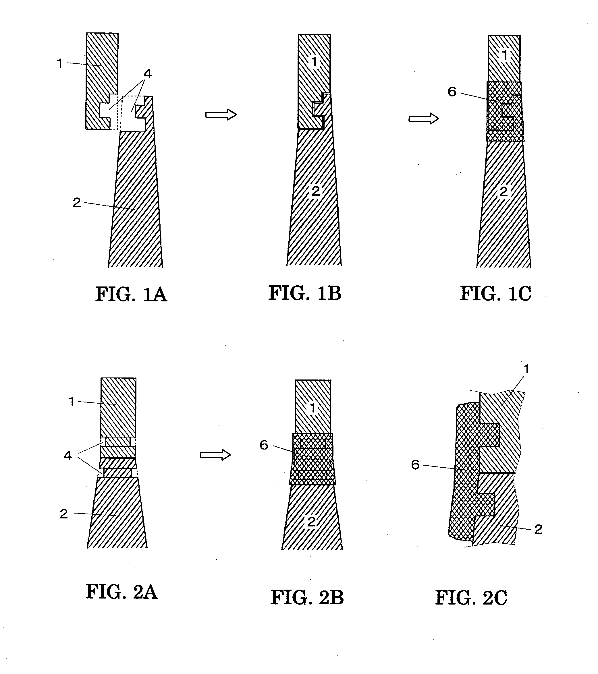
[0025]First, a first bonding / fixing technique concerned with the invention is explained while referring to FIGS. 1A-1C. In the drawing, 1 is a cut-off block-like observation sample piece, and it is carried to a tip portion of a base needle 2 by a fine probe operated by the manipulator similarly to the conventional technique shown in FIG. 6B. Although FIG. 1A is a form at this time, in tip portions of a base part of the observation sample piece 1 and the base needle 2, a mutually meshing concave / convex shape 4 is already engraved. The concave shape 4 is formed by the etching working by the FIB under a state in which the observation sample piece 1 is fixed to a tip of the fine probe by the FIB-CVD. The convex shape 4 is formed by the etching working by the FIB under a state in which a tip portion of the base needle 2 is retained by a base needle retention member attached to an FIB apparatus mentioned later. As shown in FIG. 1B, these both members are fitted with the concave and convex...

embodiment 2

[0028]A second bonding / fixing technique concerned with the invention is explained while referring to FIGS. 2A-2C. A form shown in FIG. 2A is a state in which a flat base part of the observation sample piece 1 is butt-jointed to a flat tip portion of the base needle 2 and, in both members, there is formed a circumference-like groove 4 as the concave / convex shape in a position slightly spaced from the joint face. As to this groove working, similarly to the previous example, the groove shape 4 may be formed by the etching working by the FIB under the state in which the observation sample piece 1 is fixed to the tip of the fine probe by the FIB-CVD, or the groove shape 4 may be formed by the etching working by the FIB under the state in which the tip portion of the base needle 2 is retained by the base needle retention member attached to the FIB apparatus, or there may be made so as to form the groove by temporarily fixing, under a state butt-jointed in raw intact, its joint portion by ...

embodiment 3

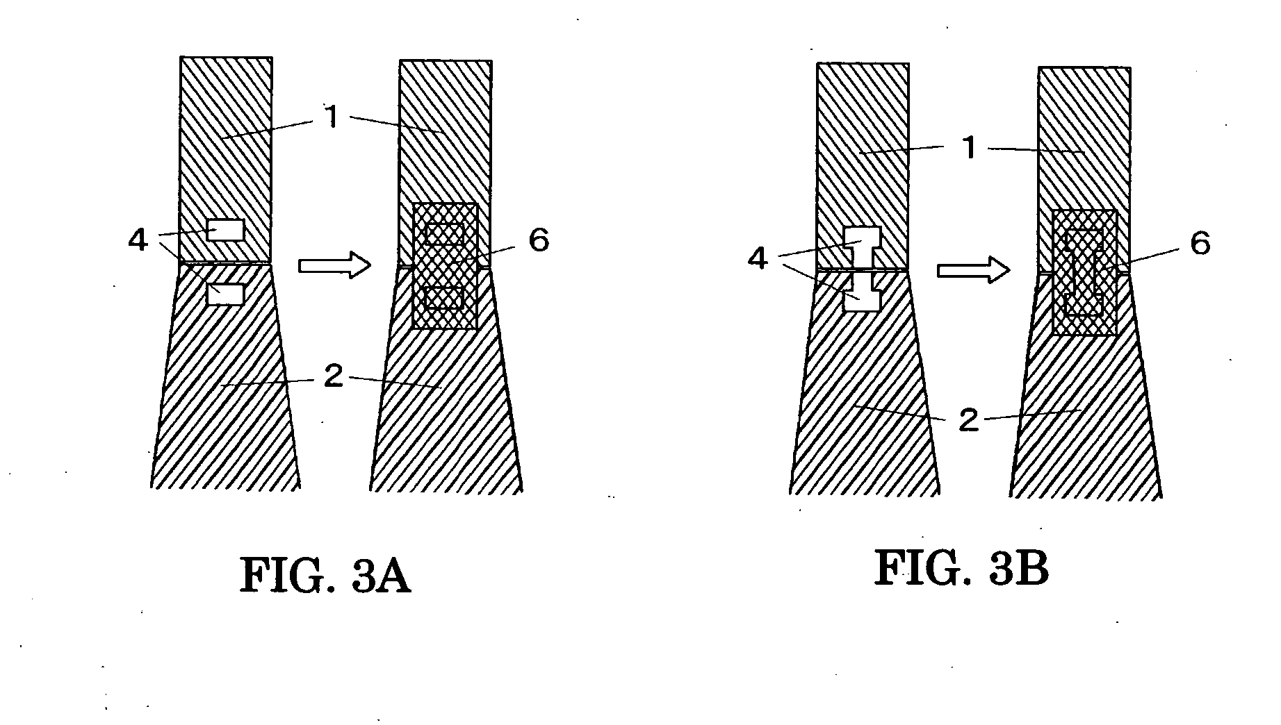
[0029]Two modified examples of the second bonding / fixing technique concerned with the invention are explained while referring to FIGS. 3A and 3B. In the previous example, although it is one which is under the state in which the flat base part of the observation sample piece 1 is butt-jointed to the flat tip portion of the base needle 2 and in which there is formed the circumference-like groove 4 in both-member positions slightly spaced from the joint face by the etching working of the FIB, the modified example shown here is one in which a hole is bored, not the groove. An embodiment shown in FIGS. 3A and 3B is one in which a quadrate hole 4 having faces intersecting perpendicularly to the needle axis is provided in both members by the etching working of the FIB. The deposition layer 6 is formed by the deposition working of the FIB so as to extend over these quadrate holes 4 formed in both members, and they are fixed by a bridge of the clamp form. A left side of FIG. 3A is a view sho...


PUM

PropertyMeasurementUnit
lengthaaaaaaaaaa
thicknessaaaaaaaaaa
lengthaaaaaaaaaa

Abstract

A method of manufacturing a sample for an atom probe analysis of the invention is made one going through a step of manufacturing a concave/convex structure in both of a base needle and a transplantation sample piece by an etching working of an FIB, a step of jointing mutual members, and a step of bonding such that the concave/convex structure becomes a mesh form by a deposition working of the FIB.

Description

RELATED APPLICATIONS[0001]This application claims priority under 35 U.S.C. §119 to Japanese Patent Application No. JP2006-303500 filed on Nov. 9, 2006, the entire content of which is hereby incorporated by reference.BACKGROUND OF THE INVENTION[0002]The present invention relates to a method of manufacturing a sample for an atom probe analysis by an FIB, and an apparatus capable of easily implementing that method.[0003]As means capable of directly observing an atomic arrangement of a needle point, there is developed an atom probe (AP: Atom Probe) that is a composite instrument of a mass spectrometer capable of detecting a single ion and a field-ion microscope (FIM). The AP is a solitary device capable of analyzing an electronic state, the atomic arrangement and a composition distribution of the needle point. Since a field evaporation orderly proceeds in every atom layer from a surface first layer, by the AP it is possible to investigate a composition or the composition distribution of...

Claims


Application Information

Patent Timeline
Patent Type & Authority Applications(United States)
IPC IPC(8): C23C14/46
CPCG01N1/32H01J2237/20H01J2237/31732H01J2237/3174B82Y35/00G01Q60/38G01Q70/12G01Q70/10H01J2237/3109
Inventor KAITO, TAKASHI
Owner HITACHI HIGH TECH SCI CORP
Why Eureka
Try Eureka