Low cost and low variation oscillator

a low-cost, oscillator technology, applied in the field of oscillators, can solve the problems of significant problems in stabilizing the oscillator frequency, driving up both the cost of fabrication and the cost of operation, and essentially temperature-variant integrated circuit capacitors

Active Publication Date: 2008-11-27
ATMEL CORP
View PDF4 Cites 16 Cited by
  • Summary
  • Abstract
  • Description
  • Claims
  • Application Information

AI Technical Summary

Problems solved by technology

However, integrated circuit capacitors are essentially temperature invariant.
The variation in the time constant based on temperature variation thus creates significant problems in stabilizing the oscillator frequency.
Howeve

Method used


Image

  • Low cost and low variation oscillator
  • Low cost and low variation oscillator
  • Low cost and low variation oscillator

Examples


Embodiment Construction

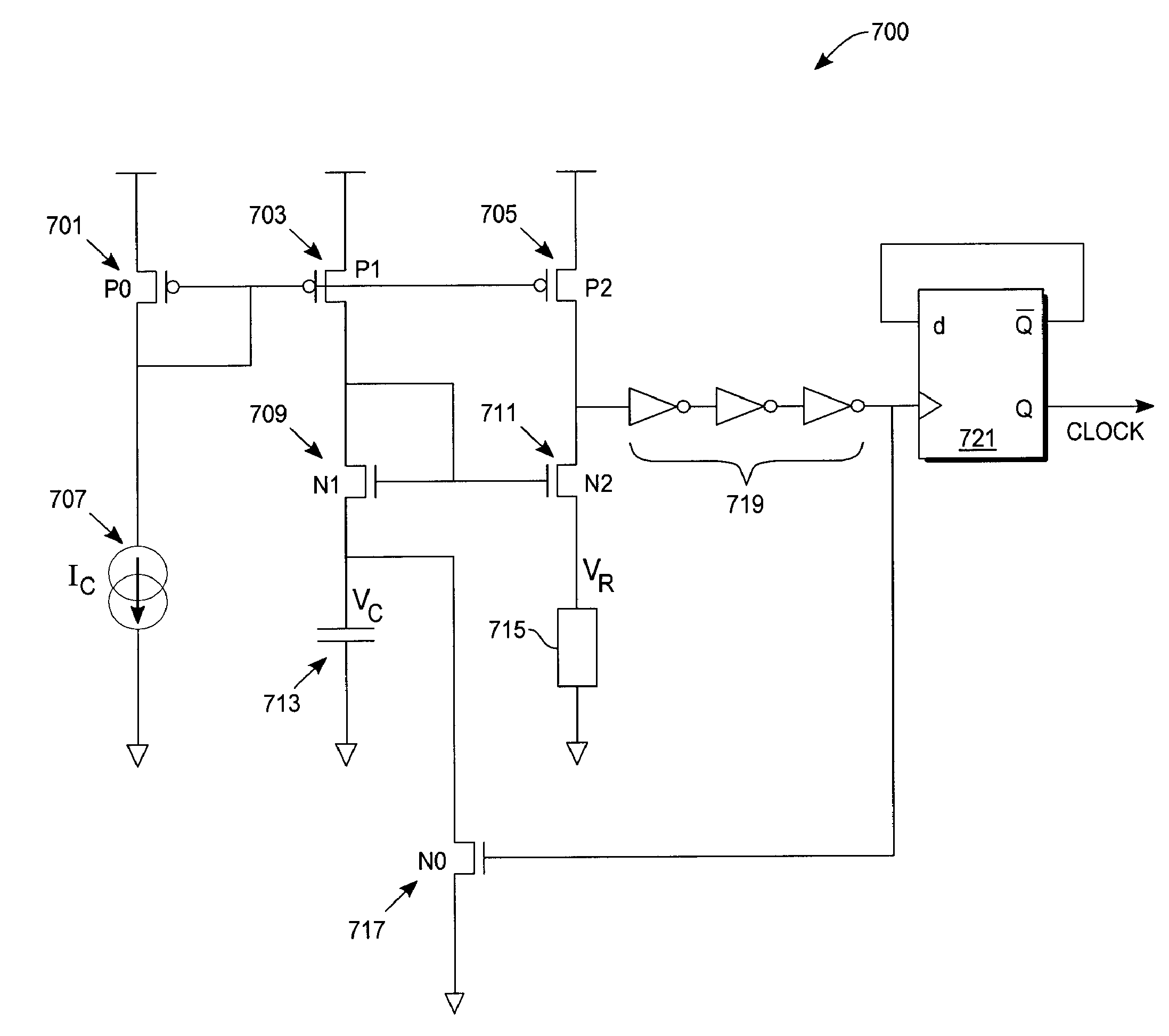
[0022]In exemplary embodiments described herein, the invention is an oscillator comprised of a delay generation circuit which generates an output signal which propagates through a plurality of inverters coupled in series. The delay generation circuit utilizes two current mirror branches. The two current mirror branches each charge a capacitor and a resistor thus producing an RC time constant. A build-up of current through the resistor to a magnitude equal to the current mirror value produces a threshold voltage at an output of the delay generation circuit. The output of the delay generation circuit is fed to a first of the plurality of inverters in series. A final inverter in the series produces an output which clocks a D-type flip-flop. The D-type flip-flop is configured to toggle. An output of the D-type flip-flop produces a clock signal. The last inverter output is further coupled to a control input of a transistor to short-circuit the capacitor. Shorting the capacitor produces a...


PUM


Abstract

An oscillator circuit for use in integrated circuits. The oscillator circuit includes a delay generation circuit having a current mirror with at least a first current mirror branch and a second current mirror branch, a current source coupled to the first current mirror branch, a capacitive element coupled to the first current mirror branch; and a resistive element coupled to the second current mirror branch. The oscillator circuit further includes a plurality of inverting elements coupled in series with one another and a transconducting element coupled to an output of the plurality of inverting elements. The transconducting element is configured to discharge the capacitive element. A latching element is coupled to latch to an output signal of the plurality of inverting elements.

Description

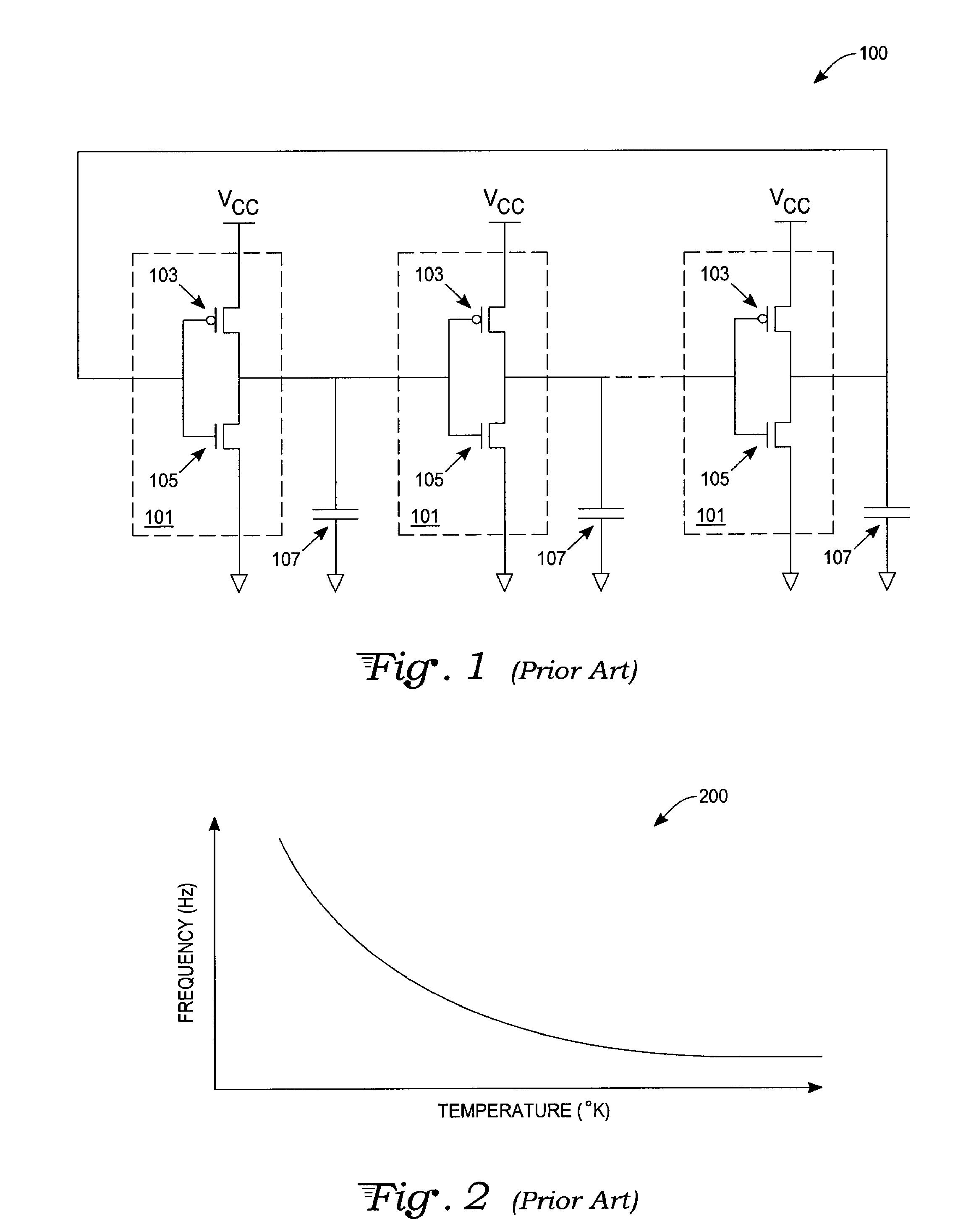
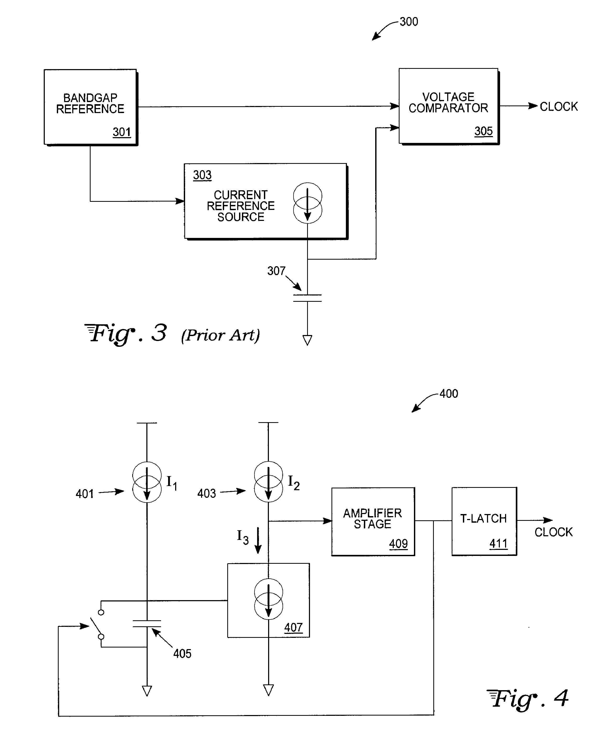
TECHNICAL FIELD[0001]The invention relates generally to an oscillator fabricated in integrated circuits. More specifically, the invention relates to an oscillator that produces an output frequency independent of transistor semiconductor processes, power supply variation, and biasing current.BACKGROUND ART[0002]Currently, the most common way to design an integrated oscillator is to use the ubiquitous ring oscillator circuit. As described below, the ring oscillator cell uses an odd number of CMOS inverters. However, a generated frequency of the typical ring oscillator circuit is strongly dependent not only upon the number of CMOS inverters used in the circuit, but upon a temperature of the integrated circuit itself.[0003]In integrated circuit devices, the resistance of load devices is highly temperature sensitive. Variations in resistance are due primarily to changes in surface carrier mobility with temperature. However, integrated circuit capacitors are essentially temperature invari...

Claims


Application Information

Patent Timeline
IPC IPC(8): H03K3/26H03K3/03
CPCH03K3/011H03K3/0231H03K3/354H03K5/133H03K5/1565H03K2005/0013H03K2005/00143H03K2005/00202
Inventor FORT, JIMMYCUENCA, MICHELPAYRARD, DANIEL
Owner ATMEL CORP
Why Eureka
Try Eureka