Optical Fiber with Tin Doped Core-Cladding Interface

a technology of optical fiber and core cladding, applied in the field of tin-doped optical fiber, can solve the problems of reducing the accuracy of electronic sensors, difficult powering electronic sensors, and unreliable electrical powering of electronic sensors

Active Publication Date: 2008-11-27
BAKER HUGHES INC
View PDF9 Cites 14 Cited by
  • Summary
  • Abstract
  • Description
  • Claims
  • Application Information

AI Technical Summary

Benefits of technology

[0009]The present invention is also directed towards a method of making an optical fiber utilizing modified chemical vapor deposition comprising the steps of providing a glass perform tube; depositing a plurality of depressed-index cladding layers along the inner surface of the glass perform tube; depositing fewer layers of tin-doped silica on the exposed surface of the depressed-index cladding layers; depositing a relatively thick, single layer of pure silica on the exposed surface of the doped silica layers; and collapsing the tube to form a solid core perform.

Problems solved by technology

For systems that require a string of electronic sensors over a long distance, e.g., twenty to thirty kilometers or longer, powering the electronic sensors becomes difficult.
Powering electronic sensors electrically has been unreliable in the petroleum and gas industry.
For example, electric wires spanning long distances are subject to a significant amount of interference and noise, thereby reducing the accuracy of the electronic sensors.
However, when conventional optical fibers such as germanium-doped silica fibers are exposed to the intense heat, pressure, and hydrogen-rich environment of an oil well attenuation losses increase.
As temperatures in a typical oil or gas well generally range from slightly less than surface temperature near the surface to between about 90 to 250 degrees Centigrade (C), and possibly 350 degrees C., conventional germanium-doped optical fibers are generally not sufficiently stable for prolonged use at depth in a well.
However, at lower temperatures, such as the temperature in the upper portion of a well, attenuation losses from molecular hydrogen can be relatively large.

Method used


Image

  • Optical Fiber with Tin Doped Core-Cladding Interface
  • Optical Fiber with Tin Doped Core-Cladding Interface
  • Optical Fiber with Tin Doped Core-Cladding Interface

Examples


Embodiment Construction

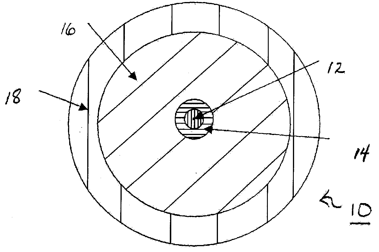
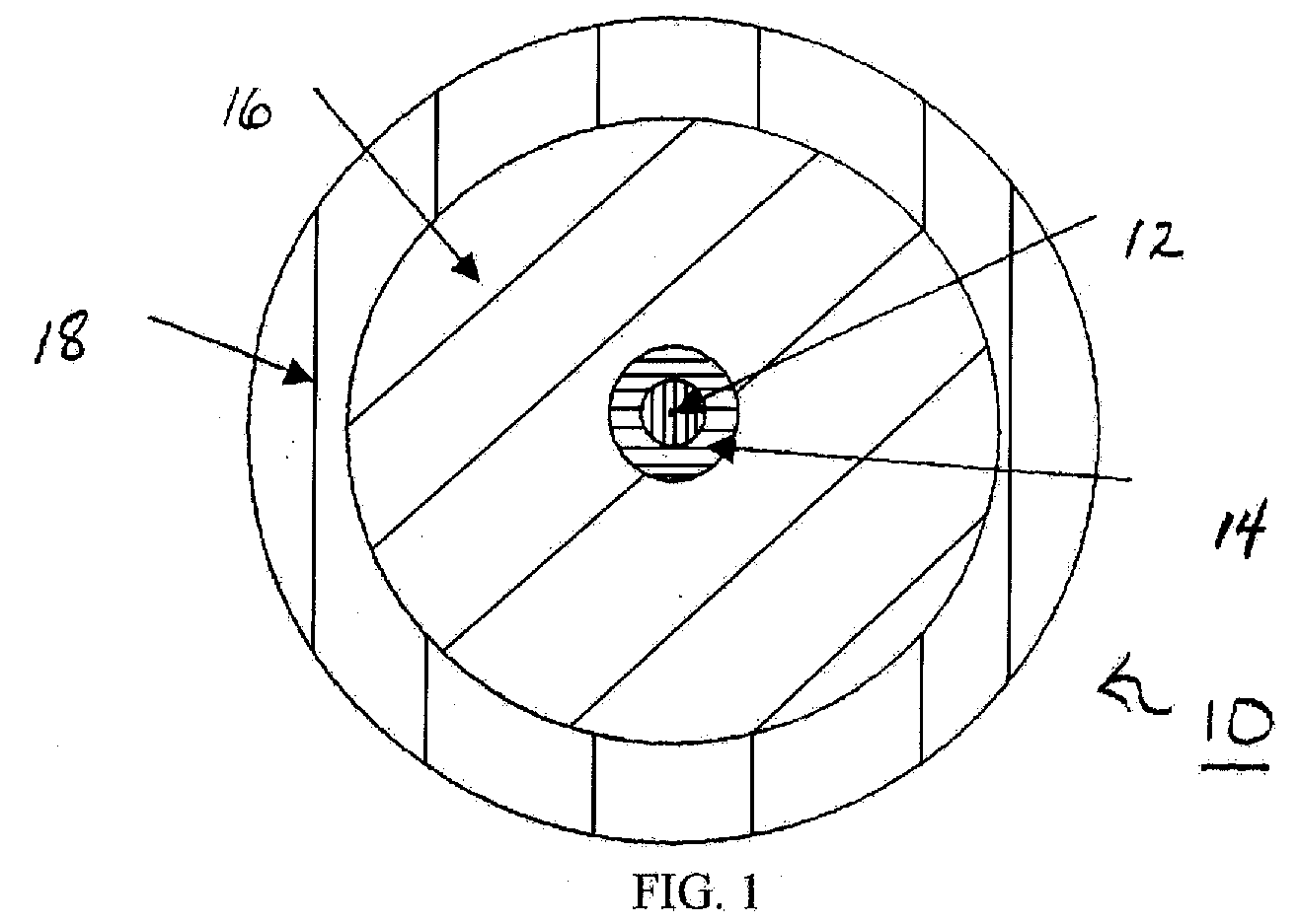
[0022]As illustrated in the accompanying drawings and discussed in detail below, the present invention is directed to an optical fiber. As shown in FIG. 1, optical fiber 10 generally includes a substantially pure silica glass core 12, a concentric tin-doped core / cladding interface region 14, a concentric fluorine-doped depressed cladding layer 16, and an optional outer cladding layer 18. The tin-doped core / cladding interface region 14 comprises a low concentration gradient of tin dioxide, which advantageously results in a de minimis refractive index change, resistance to hydrogen incursion, and thermal stability of any fiber Bragg gratings written into interface 14.

[0023]Optical fiber 10 employed in the present invention may include any suitable optical fiber including, but not limited to a single-mode or multi-mode optical fiber. Core 12 may be any substantially pure silica glass core known in the art. In one embodiment, core 12 may be a “defect free” pure silica core. The core / cla...


PUM

PropertyMeasurementUnit
diameteraaaaaaaaaa
refractive index n2aaaaaaaaaa
distanceaaaaaaaaaa

Abstract

The present invention concerns an optical fiber 10 comprising a substantially pure silica glass core 12, a concentric tin-doped core/cladding interface region 14, and a concentric fluorine-doped depressed cladding layer 16. The tin-doped core/cladding interface region 14 comprises a low concentration gradient of tin dioxide, which advantageously results in a de minimis refractive index change, resistance to hydrogen incursion, and thermal stability of any fiber Bragg gratings written into the interface region 14.

Description

FIELD OF THE INVENTION[0001]The invention relates generally to optical fiber technologies. In particular, the invention relates to tin-doped optical fibers that resist attenuation losses at high temperatures.BACKGROUND OF THE INVENTION[0002]Available electronic sensors measure a variety of values, such as, pH, color, temperature, or pressure, to name a few. For systems that require a string of electronic sensors over a long distance, e.g., twenty to thirty kilometers or longer, powering the electronic sensors becomes difficult. Conventionally, the powering of electronic sensors requires running electrical wire from a power source to each of the electronic sensors. Powering electronic sensors electrically has been unreliable in the petroleum and gas industry. For example, electric wires spanning long distances are subject to a significant amount of interference and noise, thereby reducing the accuracy of the electronic sensors.[0003]Optical fibers have become the communication medium...

Claims


Application Information

Patent Timeline
Patent Type & Authority Applications(United States)
IPC IPC(8): G02B6/02G02B6/04
CPCC03B37/01807C03B2201/12C03B2201/30C03C13/046G02B6/021G02B6/02119G02B6/0219G02B6/03627
Inventor HOMA, DANIEL
Owner BAKER HUGHES INC
Why Eureka
Try Eureka