Prosthetic Heart Valve

a heart valve and prosthesis technology, applied in the field of prosthetic heart valves, can solve the problems of relative obstruction of blood flow, cardiac valve abnormalities, emergency surgery, etc., and achieve the effect of minimizing the likelihood of pocket formation and extending the range of motion

Inactive Publication Date: 2008-11-27
MEDICAL ENTREPRENEURS II
View PDF54 Cites 85 Cited by
  • Summary
  • Abstract
  • Description
  • Claims
  • Application Information

AI Technical Summary

Benefits of technology

[0018]Certain other improvements provided by the present invention address the problem of thrombus formation within the confines of the covering which is placed over the valve's wireform and stent. In particular, the subject improvements minimize or prevent, among other things, the formation of a pocket between the covering and the inner surface of the stent's commissure extensions when the extensions are tensioned inward by the forces imposed on the valve under normal operating conditions.
[0019]In one variation of the inventive prosthetic valves, the stent structure has commissure extensions aligned within the commissures peaks of the wireform wherein the extensions are angled slightly inward to define a pre-fixed angle, typically within the range from about 0° to about 10°, with an inner wall of the stent. In this way, the range of motion which the commissure extensions are subject to is minimized, thereby minimizing the likelihood of the formation of a pocket between the covering and the stent wall. Angling of the commissures extensions may be accomplished by coupling separately formed commissure extensions to the stent base by mechanical means, such as a stitch, wherein their coupling defines a flexible joint. Alternatively, the extensions may be monolithically formed with the stent at the prefixed or predefined angle. In either case, the flexible point of joinder between the stent commissures and the stent base allow the commissures to flex or bend inward when subject to the normal operating forces exerted on the valve and its leaflets. To further ensure against the formation of a pocket between the cloth material and the inner surface of the commissure extensions, covering is provided substantially flush with the inner surface. This may be accomplished by the placement of a stitch between the two.

Problems solved by technology

Congenital valve abnormalities may be well-tolerated for many years only to develop into a life-threatening problem in an elderly patient, or may be so severe that emergency surgery is required within the first few hours of life.
High blood pressure may also lead to cardiac valve abnormalities.
In addition, damage to the ventricle from prior heart attacks (i.e., myocardial infarction secondary to coronary artery disease) or other heart diseases (e.g., cardiomyopathy) can distort the valve's geometry causing it to dysfunction.
Valve stenosis is present when the valve does not open completely causing a relative obstruction to blood flow.
Stenosis and insufficiency may occur concomitantly in the same valve or in different valves.
Both of these conditions increase the workload on the heart and are very serious conditions.
If left untreated, these conditions can lead to debilitating symptoms including congestive heart failure, permanent heart damage and ultimately death.
Many dysfunctional valves, however, are diseased beyond the point of repair.
Dysfunction of the left-sided valves—the aortic and mitral valves—is typically more serious since the left ventricle is the primary pumping chamber of the heart.
The aortic valve is more prone to stenosis, which typically results from buildup of calcified material on the valve leaflets and usually requires aortic valve replacement.
Rheumatic valve are not suitable for any type of repair procedure and, accordingly, are almost always replaced.
Presently, mechanical valves have the longest durability of available replacement heart valves.
Continuous use of anticoagulants can be dangerous, as it greatly increases the user's risk of serious hemorrhage.
In addition, a mechanical valve can often be audible to the recipient and may fail without warning, which can result in serious consequences, even death.
However, naturally occurring processes within the human body may stiffen or calcify the leaflets over time, particularly at high-stress areas of the valve such as at the commissure junctions between the valve leaflets and at the peripheral leaflet attachment points or “cusps” at the outer edge of each leaflet.
Further, the valves are subject to stresses from constant mechanical operation within the body.
Accordingly, these types of prosthetic valves wear out over time and need to be replaced.
Bioprosthetic and synthetic leaflet heart valves are also considerably more difficult and time consuming to manufacture than mechanical heart valves as they are made substantially by hand by highly trained and skilled personnel.
The mismatch is often due to the variabilities in the shape of the stent ring.
The forming and welding processes make the stent susceptible to “spring-back”, i.e., slight deformation undergone by the ring into a less than circular shape overtime.
The tension applied to the stent upon suturing it together with the wireform, and that experienced during normal functioning of the valve, makes the stent further susceptible to spring-back.
This mismatch 2 often leads to the wireform 4 becoming offset in either direction from the stent ring 6, which in turn leads to instability between the components.
The instability results in uneven stress points, particularly on the valve leaflets, and subsequent expedited wearing of the valve.

Method used


Image

  • Prosthetic Heart Valve
  • Prosthetic Heart Valve
  • Prosthetic Heart Valve

Examples


Embodiment Construction

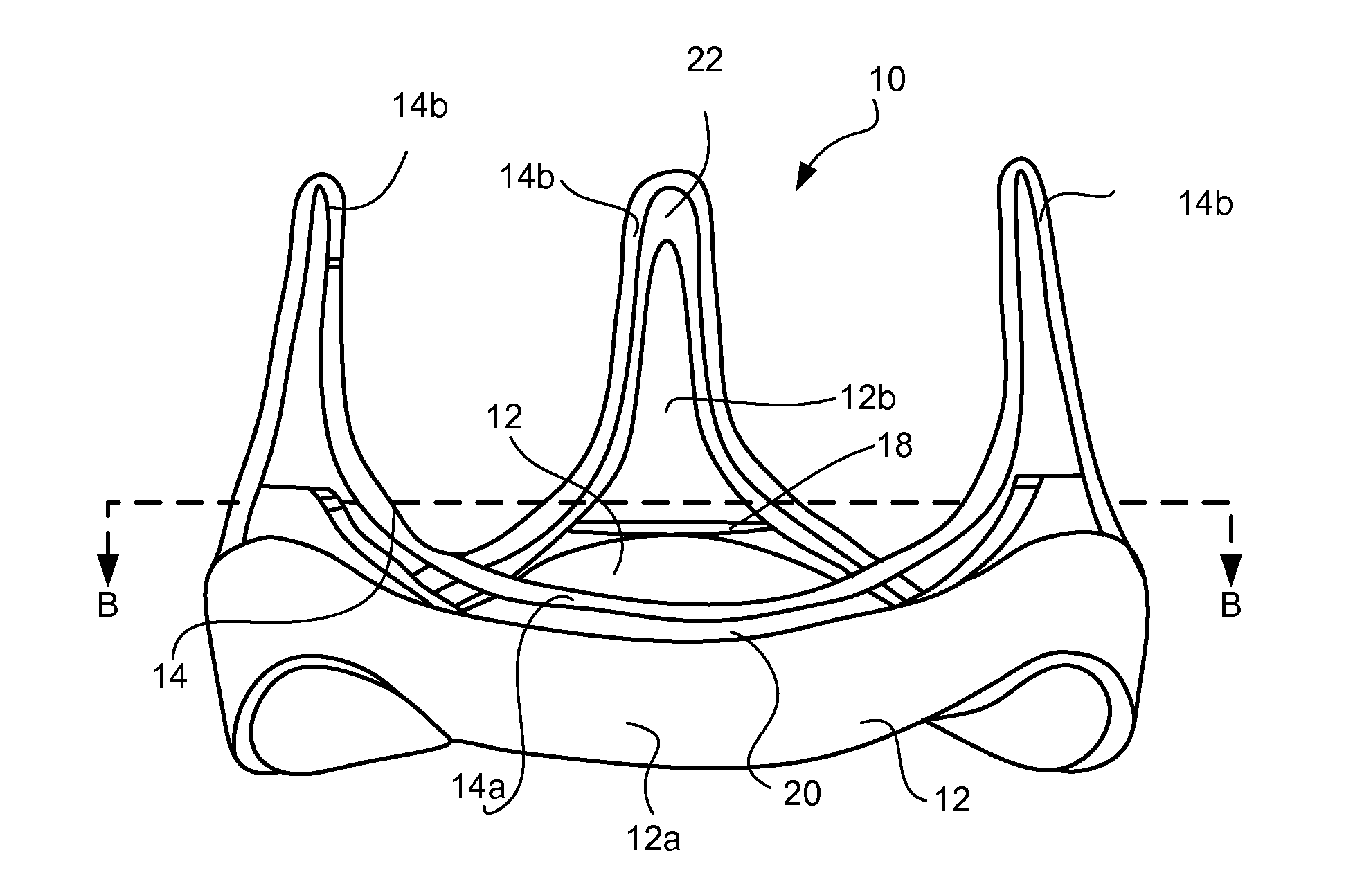
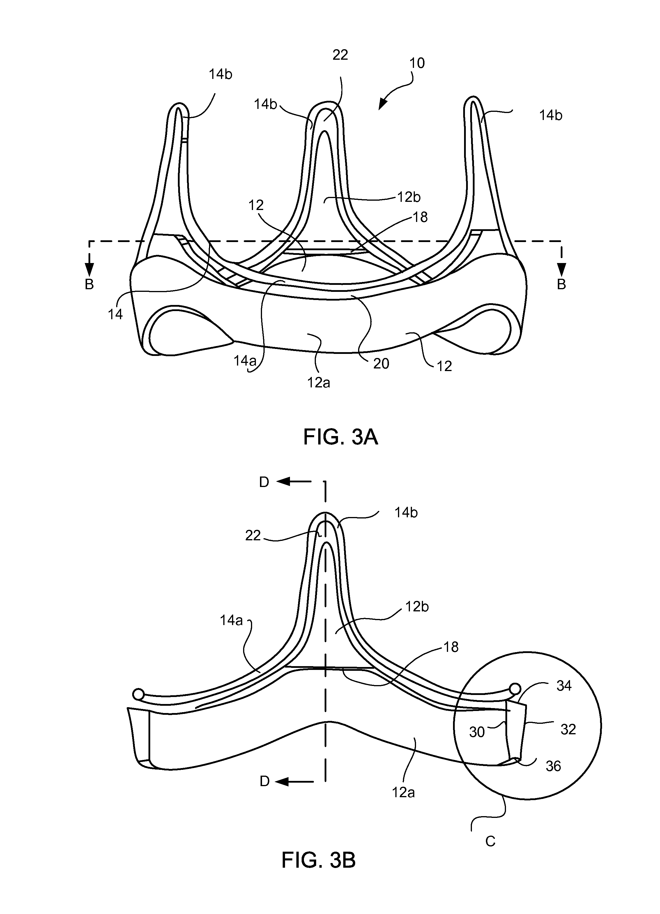
[0030]The present invention will now be described in greater detail with reference to FIGS. 3A-3D and 4, and by way of the following description of exemplary embodiments and variations of the novel devices, systems and methods. The invention generally includes an implantable prosthetic heart valve 10 having an annular stent in the form of a ring 12 and an annular wireform or frame 14 wherein the stent and wireform have substantially similar diameters. The wireform has an alternating pattern of arcuate cusps 14a and upstanding commissures 14b, whereby the number of each is typically three so as to most closely match the structure and function of the natural heart valve, e.g., the aortic valve, which it is intended to replace (although a three-leaflet valve of the present invention is also suitable to replace bicuspid valves, e.g. mitral valves). This undulating pattern mimics the natural contour of leaflet attachment and serves to support the prosthetic leaflets (not shown) within th...


PUM


Abstract

The present invention includes prosthetic heart valves having flexible leaflets and methods for fabricating the valves which improve upon the prior art.

Description

FIELD OF THE INVENTION[0001]The present invention is directed to prosthetic heart valves having flexible leaflets made of tissue or synthetic materials, and is also directed to improved methods of making such valves.BACKGROUND OF THE INVENTION[0002]The human heart has four major valves which control the direction of blood flow in the circulation. The aortic and mitral valves are part of the “left” heart and control the flow of oxygen-rich blood from the lungs to the body, while the pulmonic and tricuspid valves are part of the “right” heart and control the flow of oxygen-depleted blood from the body to the lungs. The aortic and pulmonic valves lie between a pumping chamber (ventricle) and major artery, preventing blood from leaking back into the ventricle after it has been ejected into the circulation. The mitral and tricuspid valves lie between a receiving chamber (atrium) and a ventricle preventing blood from leaking back into the atrium during ejection.[0003]Heart valves may exhi...

Claims


Application Information

Patent Timeline
Patent Type & Authority Applications(United States)
IPC IPC(8): A61F2/24
CPCA61F2/2409A61F2/2418A61F2220/0058A61F2220/0075A61F2250/0039
Inventor YANG, JUNHUYNH, VANESTES, MICHAEL
Owner MEDICAL ENTREPRENEURS II
Why Eureka
Try Eureka