Plasma generator and workpiece processing apparatus using the same

a workpiece and generator technology, applied in the field of plasma generators, can solve the problems of unstable discharge characteristics, inability to subject a large-surface area workpiece or a group of workpieces to plasma exposure, and increase in cost, so as to reduce the plasma disappearance rate, suppress plasma cooling, and facilitate control

Inactive Publication Date: 2008-12-04
SAIAN CORP
View PDF13 Cites 15 Cited by
  • Summary
  • Abstract
  • Description
  • Claims
  • Application Information

AI Technical Summary

Benefits of technology

[0009]That is, the present invention is directed to a plasma generator usable for a processing of a target object, such as a surface modification of a substrate, wherein the plasma generation nozzle is formed in a configuration suitable for plasma generation, for example, in a structure adapted to induce a glow discharge between inner and outer electrodes disposed in concentric relation to each other so as to generate a plasma, and supply a processing gas between the inner and outer electrodes so as to emit a plasmatized gas from a ring-shaped spout port, and wherein the plasma generation nozzle is provided with the cover member at a distal end thereof to suppress scattering of the plasma by the cover member. Specifically, the cover member is prepared by forming, in a plate-shaped member, an opening which allows the spout port of the plasma generation nozzle to be uncovered. Then, the cover member is attached to cover the plasma generation nozzle formed, for example, in a cylindrical shape, so that a continuous surface, such as a flat or curved continuous surface, having an area greater than that of the distal end surface of the pla...

Problems solved by technology

Although the plasma generation nozzle disclosed in the Publication 1 has a configuration suitable for plasma generation, i.e., a configuration capable of generating high-density plasma under atmospheric pressures, the configuration is unsuitable for processing a workpiece having a relatively large surface area or processing a plurality of workpieces all together.
Thus, there is a problem of being unable to subject a large-surface area workpiece or a group of workpieces to plasma ex...

Method used


Image

  • Plasma generator and workpiece processing apparatus using the same
  • Plasma generator and workpiece processing apparatus using the same
  • Plasma generator and workpiece processing apparatus using the same

Examples


Embodiment Construction

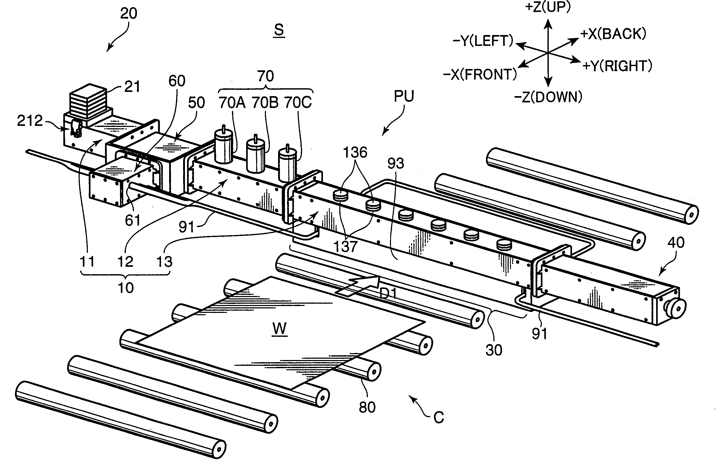
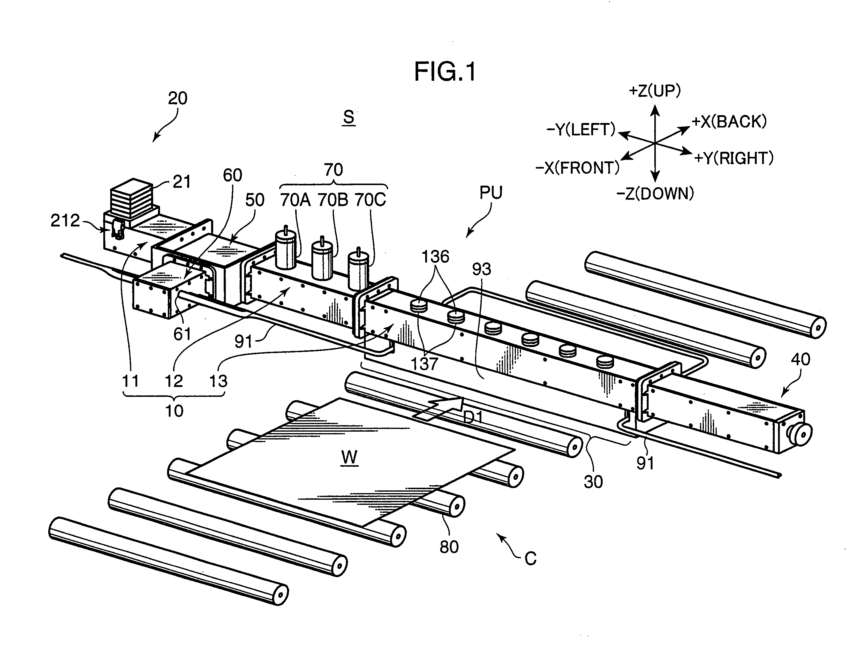
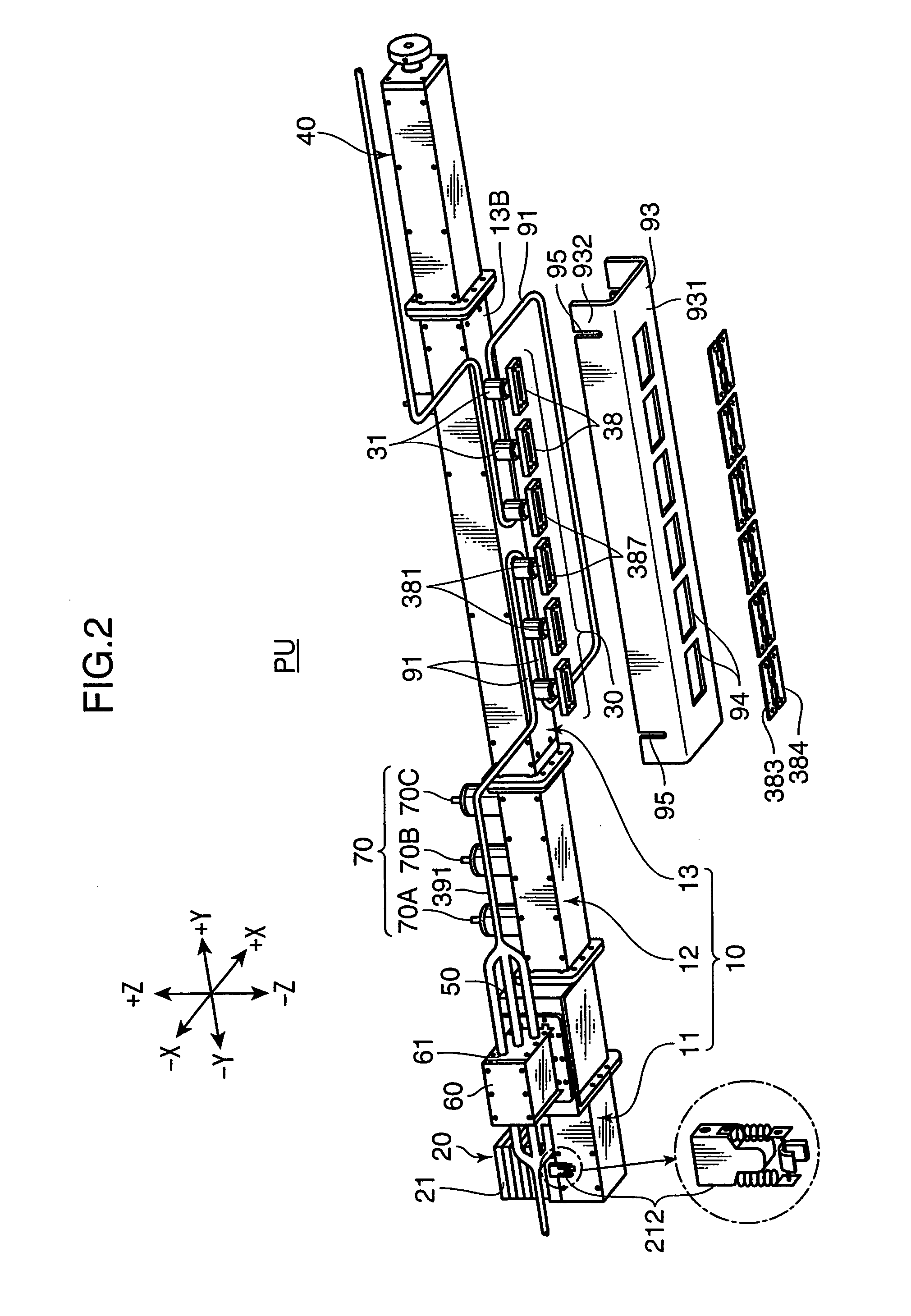
[0025]FIG. 1 is a perspective view showing a general structure of a workpiece processing apparatus S according to one embodiment of the present invention. This workpiece processing apparatus S comprises a plasma generation unit PU (plasma generator) adapted to generate plasma and emit the plasma toward a workpiece W which is a target object, and a carrying mechanism C (carrying means) adapted to carry the workpiece W along a predetermined route passing through an exposure zone to be exposed to the plasma. FIG. 2 is an exploded perspective view of the plasma generation unit PU when viewed from a direction different from that in FIG. 1, and FIG. 3 is a partially cut-out side view of the plasma generation unit PU. The following description will be made on an assumption that the X-X direction, the Y-Y direction and the Z-Z direction in FIGS. 1 to 3 are, respectively, a frontward / rearward (longitudinal) direction, a rightward / leftward (lateral) direction and an upward / downward (vertical)...


PUM

PropertyMeasurementUnit
Electrical conductoraaaaaaaaaa
Areaaaaaaaaaaa
Surface areaaaaaaaaaaa

Abstract

Disclosed are a plasma generator and a workpiece processing apparatus, wherein an adapter 38 is attached to a distal end of each of a plurality of plasma generation nozzles 31 to convert a spot-shaped spout port of the plasma generation nozzle 31 to a lengthwise sport port 387, and a cover member 93 is provided to cover the plasma generation nozzles 31 so as to allow a narrow space to be defined between the cover member 93 and a workpiece, whereby plasma spouted from the spout port 387 is retained in the space in such a manner as to hit against and rebound from the workpiece into the space. This makes it possible to subject a workpiece having a relatively large surface area to plasma exposure in a uniform manner, while suppressing cooling of plasma in the space to allow the plasma to survive for a relatively long period of time (reduce a plasma disappearance rate) so as to provide enhanced efficiency of plasma exposure.

Description

BACKGROUND OF THE INVENTION[0001]1. Field of the Invention[0002]The present invention relates to a plasma generator designed to emit plasma toward a target object (workpiece), such as a substrate, so as to carry out cleaning, modification or other processing of a surface of the target object. The present invention also relates to a workpiece processing apparatus using the plasma generator.[0003]2. Description of the Related Art[0004]There has been known a workpiece processing apparatus designed to expose a target object (workpiece), such as a semiconductor substrate, to plasma so as to carry out a processing of a surface of the workpiece, such as removal of organic contaminants on the surface, modification of the surface, etching of the surface, or formation or removal of a thin film on the surface. For example, JP 2003-197397A (Publication 1) discloses a plasma processing apparatus using a plasma generation nozzle including an inner electrode and an outer electrode which are dispos...

Claims


Application Information

Patent Timeline
IPC IPC(8): H05H1/34
CPCH01J37/32192H01J37/32825H01L21/67069H05H1/46H05H1/26B01J19/08
Inventor MIKE, MASAAKIMANKAWA, HIROFUMIMASUDA, SHIGERUHAYASHI, HIROFUMI
Owner SAIAN CORP
Why Eureka
Try Eureka