Unlock instant, AI-driven research and patent intelligence for your innovation.

Discrimination method for optical disc types and optical disc apparatus

Inactive Publication Date: 2008-12-04
FUNAI ELECTRIC CO LTD
View PDF10 Cites 3 Cited by
  • Summary
  • Abstract
  • Description
  • Claims
  • Application Information

AI Technical Summary

Benefits of technology

[0013]It is an object of the present invention to provide an optical disc type discrimination method for discriminating with high accuracy a type of an optical disc between two optical discs having different thicknesses of transparent layers for which the same wavelength of laser light is used like the case of a BD and an HD-DVD, and to provide an optical disc apparatus using the discrimination method.
[0015]According to this structure, it is possible to discriminate accurately optical discs having different thicknesses of transparent layers for which the same wavelength of laser light is used.
[0016]Thus, the spherical aberration correction can be performed appropriately so that deterioration of accuracy in reading and writing information can be suppressed.

Problems solved by technology

In this case, it is difficult to determine correctly a type of the loaded optical disc.

Method used


Image

  • Discrimination method for optical disc types and optical disc apparatus
  • Discrimination method for optical disc types and optical disc apparatus
  • Discrimination method for optical disc types and optical disc apparatus

Examples


Embodiment Construction

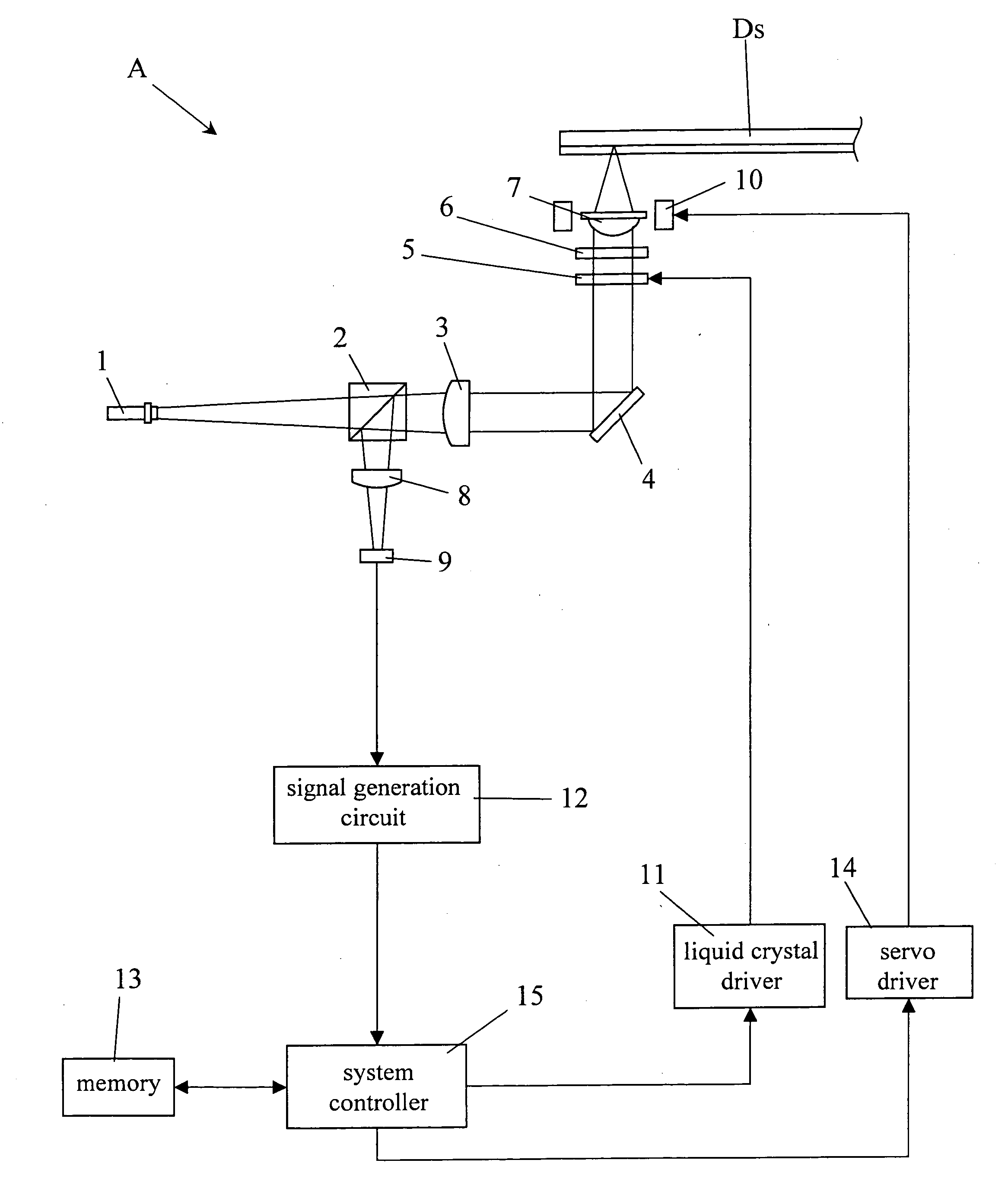
[0034]Hereinafter, an embodiment of the present invention will be described with reference to the attached drawings. FIG. 1 is a diagram showing a structure of an example of an optical disc apparatus according to the present invention. An optical disc apparatus A shown in FIG. 1 can reproduce information recorded on two types of optical discs including a BD medium and an HD-DVD medium. Note that the optical disc is denoted by Ds in FIG. 1 for convenience sake.

[0035]The optical disc apparatus A has a blue color laser light source 1, a polarizing beam splitter 2, a collimator lens 3, a mirror 4, a liquid crystal element 5, a quarter wavelength plate 6, an objective lens 7, a cylindrical lens 8, a light receiving part 9, an actuator 10, a liquid crystal driver 11, a signal generation circuit 12, a memory 13, a servo driver 14 and a system controller 15.

[0036]The blue laser light source 1 emits a blue color laser beam (having a wavelength of 405 nm). The blue laser beam emitted from the...


PUM


Abstract

An optical disc apparatus, which discriminates types of optical discs having different thicknesses of transparent layers by using the same wavelength of laser light, includes an aberration correction unit for correcting spherical aberration, an objective lens for condensing the laser beam onto a recording surface of an optical disc, an actuator for moving the objective lens with respect to the optical disc, a signal detection unit for delivering a focus error signal or a sum light signal, a control unit for controlling the aberration correction unit, the actuator and the signal detection unit. The control unit drives and sets the aberration correction unit so that the laser beam has a predetermined spherical aberration, performs a focus search operation of moving the objective lens to approach the optical disc in a state where the laser beam is projected onto the optical disc, and uses at least one of the focus error signal and the sum light signal delivered from the signal detection unit at a just focus position as an optical disc type discrimination signal.

Description

[0001]This application is based on Japanese Patent Application No. 2007-139823 filed on May 28, 2007, and the contents of which are hereby incorporated by reference.BACKGROUND OF THE INVENTION[0002]1. Field of the Invention[0003]The present invention relates to a discrimination method for discriminating optical discs having different thicknesses of transparent layers for which the same wavelength of laser light is used and to an optical disc apparatus using the discrimination method.[0004]2. Description of Related Art[0005]An optical disc apparatus is known well as using an optical disc as a recording medium for storing audio data and / or video data. The optical disc apparatus can read and write information on the optical disc by projecting a laser beam to the same.[0006]The optical disc apparatus always detects a focus error signal for focus control. The optical disc apparatus performs a focus pull-in process based on the focus error signal so that a condensed light spot of the lase...

Claims


Application Information

Patent Timeline
IPC IPC(8): G11B7/135
CPCG11B19/12
Inventor SETONO, SHINGO
Owner FUNAI ELECTRIC CO LTD
Features
  • R&D
  • Intellectual Property
  • Life Sciences
  • Materials
  • Tech Scout
  • Unparalleled Data Quality
  • Higher Quality Content
  • 60% Fewer Hallucinations
Learn More