
Integrated Optical Waveguide Sensors With Reduced Signal Modulation

a technology of optical waveguide and signal modulation, applied in the field of integrated optical sensors for chemical and biochemical analysis, can solve the problems of reducing the sensitivity or limit of the measured signal, observing the “wobble” in the measured signal, and reducing both the sensitivity and accuracy of the measured signal. , to achieve the effect of reducing the amount of incident light entering, reducing the amount of light not coupled, and reducing the amount of superimposed incident light coupled

Inactive Publication Date: 2008-12-04
CIPHERGEN BIOSYSTEMS INC
View PDF6 Cites 31 Cited by
  • Summary
  • Abstract
  • Description
  • Claims
  • Application Information

AI Technical Summary

Benefits of technology

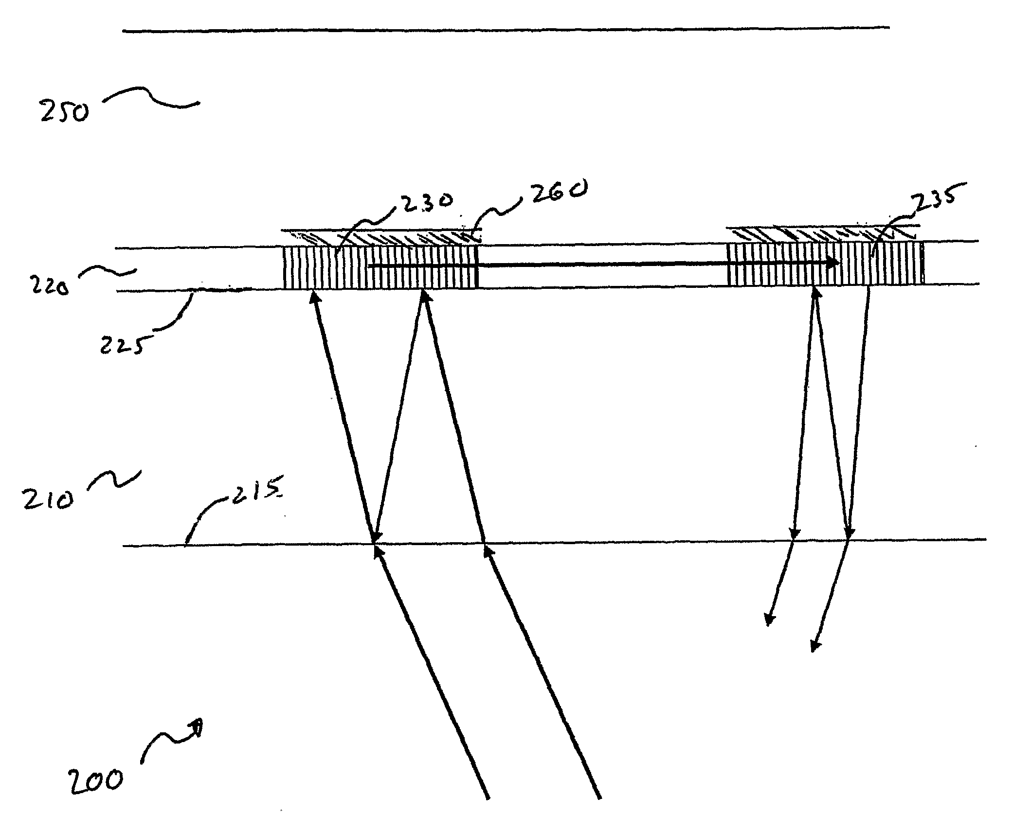
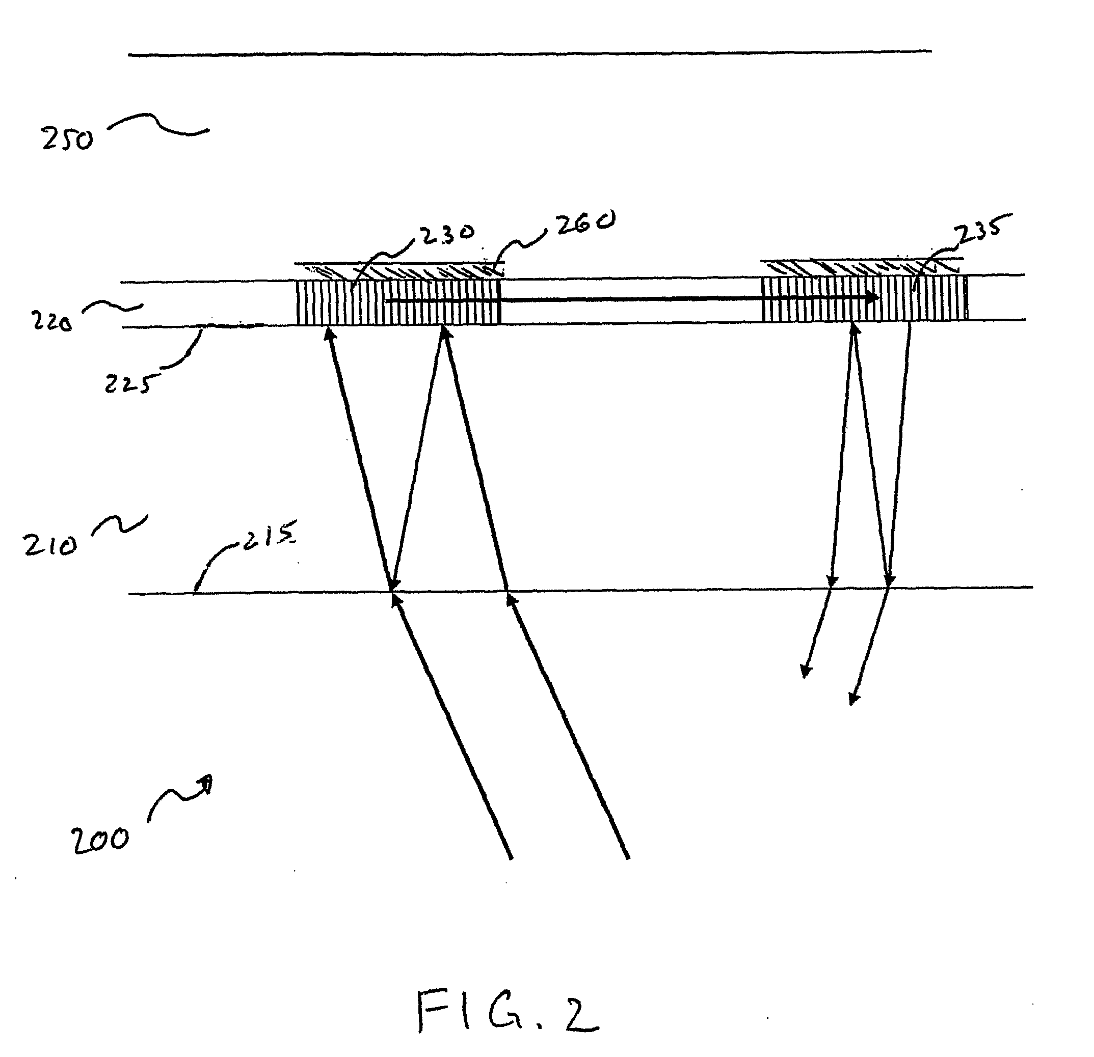
[0014]In certain embodiments, the second interface of the substrate is a substrate-air interface. In certain embodiments of the present invention, an anti-reflective layer is formed on the substrate at its second interface. In certain embodiments, the anti-reflective layer may comprise MgF2, SiO2, TiO2, or suitable combinations thereof. In certain embodiments, the anti-reflective layer may comprise two or more layers. In certain embodiments, the anti-reflective layer is dimensioned to reduce internal reflection at the second interface for a given angle of incidence.
[0017]In certain embodiments, the present invention provides a sensor module in which the substrate is suitably dimensioned with respect to the distance between the first and the second interfaces. In such sensor module embodiments, superposition between incident light that is transmitted through the substrate for coupling to at least one of the grating pads and internally reflected light in the substrate is substantially reduced. The internally reflected light is derived from the incident light that is reflected between the first and the second interfaces of the substrate. The reduction of superposition between the transmitted light and internally reflected light thereby reduces parasitic interference of the transmitted light within said substrate.
[0020]In certain embodiments, the present invention provides a sensor module comprising means for reducing the amount of incident light entering the module via the substrate, wherein said means for reduction reduces the amount of light not coupled to one of the at least one grating pads. For example, an opaque mask having at least one aperture may be disposed on the second interface of the substrate. At least one of the mask apertures may be positioned with respect to one or more grating pads on the optical waveguide on the first interface, such that at least one of the apertures allows incident light to enter the substrate through said aperture so positioned and couple with at least one of the grating pads. Similarly, at least one of the apertures may be positioned to allow excident light outcoupled from at least one of the grating pads to exit the substrate through said mask aperture so positioned.
[0021]In certain embodiments, the present invention provides a sensor module in which the first grating pad is dimensioned to reduce the amount of superimposed incident light coupled thereto. In some embodiments, the second grating pad is dimensioned to reduce the amount of superimposed excident light exiting the substrate.
[0022]In certain embodiments, the present invention provides a sensor module in which the optical waveguide film is dimensioned to act as an anti-reflective layer at the first interface of the substrate, thereby reducing internal reflection of light at the first interface for at least one wavelength and for at least one incidence angle.

Problems solved by technology

Despite the usefulness of optical waveguide sensors, certain artifacts have been observed that have tended to diminish or limit their sensitivity, or have introduced troublesome variations in the measured signal.
One such problem is the observation of “wobble” in the measured signal.
Wobble therefore diminishes both the sensitivity and accuracy of the measured signal.

Method used


Image

  • Integrated Optical Waveguide Sensors With Reduced Signal Modulation
  • Integrated Optical Waveguide Sensors With Reduced Signal Modulation
  • Integrated Optical Waveguide Sensors With Reduced Signal Modulation

Examples


Embodiment Construction

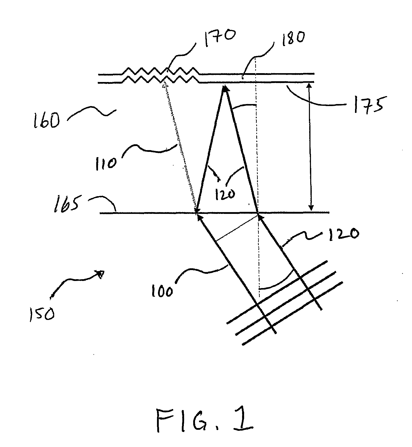
[0037]The apparatus and methods of the present invention provide improved integrated optical waveguide sensor modules that are configured to reduce the undesired phenomenon of internal parasitic interference. Such improved apparatus and methods therefore result in optical waveguide modules and associated apparatus with improved sensitivity and accuracy. In another aspect of the present invention, apparatus and methods are provided that decrease the detection limits of an integrated optical waveguide sensor module, thereby also increasing its sensitivity. Moreover, embodiments of the present invention may be used individually as well as in suitable combinations, thereby providing even greater improvements.

[0038]Parasitic interference results from the superposition of separated light beams that originate from a common source beam. Separated light beams may arise during the transmission of the original source beam through a refractive medium having internally reflective interfaces. Alt...


PUM

PropertyMeasurementUnit
optically transparentaaaaaaaaaa
internal reflectionaaaaaaaaaa
angle of incidenceaaaaaaaaaa

Abstract

The invention provides an integrated optical waveguide sensor module (200) with reduced signal modulation and increased sensitivity. An optical waveguide sensor module (200) comprises an optically transparent substrate (210) having a first and a second interface and an optical waveguide film (220) disposed on the substrate (210) with the first interface (225) therebetween, wherein the film (220) comprises at least one grating pad (235) that is optically coupled therewith. The substrate (210) and the optical waveguide film (220) are configured to reduce parasitic interference within the substrate.

Description

CROSS-REFERENCE TO RELATED APPLICATION[0001]This application claims priority to U.S. provisional patent application Ser. No. 60 / 572,556, filed May 18, 2004, which is incorporated by reference in its entirety.FIELD OF THE INVENTION[0002]This invention is in the field of chemical and biochemical analysis, and relates particularly to integrated optical sensors for chemical and biochemical analysis.BACKGROUND OF THE INVENTION[0003]The ability to detect and characterize analyte molecules with a high degree of specificity and sensitivity is of fundamental importance in chemical and biochemical analysis. Chemical and biochemical sensors have been developed that exploit a wide variety of physical phenomena in order to achieve a desirable level of sensitivity and selectivity. Such devices are particularly useful, for example, in medical diagnosis, in pharmaceutical and basic research, in food quality control, and in environmental monitoring.[0004]A particularly important class of such sensor...

Claims


Application Information

Patent Timeline
Patent Type & Authority Applications(United States)
IPC IPC(8): G02B6/00G01N21/77G02B6/12
CPCG01N21/7743G01N2021/7776G02B2006/12107
Inventor HLOUSEK, LOUISKUNZ, RINO E.VOIRIN, GUYCOTTIER, KASPAR
Owner CIPHERGEN BIOSYSTEMS INC
Learn More