Turbine vane with divided turbine vane platform

a technology of turbine vane and platform, which is applied in the direction of engine fuction, machine/engine, reaction engine, etc., can solve the problems of affecting the efficiency of the turbine engine, leaking cooling fluid through these joints, and not providing significant benefits to the normal operation of cooling fluid leakag

Inactive Publication Date: 2008-12-04
SIEMENS ENERGY INC
View PDF21 Cites 22 Cited by
  • Summary
  • Abstract
  • Description
  • Claims
  • Application Information

AI Technical Summary

Benefits of technology

[0004]This invention relates to a turbine vane with endwalls formed from two or more sections having joints along the airfoils. The sections may be configured such that the sections form releasable joints with a generally elongated airfoil of the turbine vane. The airfoil may incorporate a serpentine cooling circuit and internal impringement cooling of any variety of cooling circuits used to cool turbine airfoils. The sections may be configured to support the generally elongated airfoil and to establish cooling fluid flowpaths between the sections and the generally elongated airfoil to cool the aspects of the turbine vane proximate to the intersection of the endwalls and the generally elongated airfoil. In addition, the joints between the generally elongated airfoil and the sections may be formed from a connection system that enables forces to be transmitted from the generally elongated airfoil to the endwalls without creating thermal stresses found in conventional turbine vane fillets at the intersection between the generally elongated airfoil and the endwalls.
[0006]The first section may include a first section attachment system on the first side edge of the first section. The first section attachment system may be formed from at least one loading bearing surface for transferring loads from the generally elongated airfoil to the first section so that the first section supports and positions the turbine vane within a turbine engine. The first section attachment system may include at least one cooling fluid channel on the first side edge that is defined by the first side edge of the first section and the outer surface of the generally elongated airfoil to cool a region of the airfoil at an intersection between the generally elongated airfoil and the first section. Alternately, the airfoil may be the load bearing member and the first section may be attached to the airfoil transferring load from the section, to the airfoil. The at least one cooling fluid channel may create a cooling fluid pathway for cooling fluids to flow between the first section and the generally elongated airfoil. The first section attachment system does not include cooling fluid channels between the upstream edge and the leading edge of the airfoil and between the trailing edge of the airfoil and the downstream edge of the section. Alternatively, the design may be created such that a seal is placed in the region of the joint to minimize leakage in the region between the upstream edge and the leading edge of the airfoil and between the trailing edge of the airfoil and the downstream edge of the section.
[0009]An advantage of this invention is that the joint between adjacent endwalls for turbine vanes is positioned at the intersections of a turbine airfoil and the endwalls. Such a configuration enables the cooling fluids to be exhausted at the intersection of the turbine airfoil of the turbine vane and the endwalls, thereby cooling a region that has been traditionally difficult to cool.
[0011]Yet another advantage of this invention is that by forming an endwall from a plurality of sections that are releasably joined together, components of the turbine vane, such as the sections and airfoil, may be easily replaced in a cost effective manner.
[0013]Still another advantage of this invention is that the turbine vane eliminates stresses because a rigid connection such as that which exists in a single piece casting as the welded intersection is not required between the airfoil and endwall of conventional systems.
[0014]Another advantage of this invention is that the configuration of the turbine vane may be easily changed. For instance, the angle of position of the turbine vane may be easily changed by removing the sections of the turbine vane and replacing them with alternate sections that cause the vane to be oriented in a different angle in the gas path. Because the turbine airfoil of the turbine vane may be so easily replaced, the turbine vane may be easily customized to a particular load application for increased efficiency.

Problems solved by technology

Typically, cooling fluids leak through these joints.
The cooling fluid leakage does not ordinarily provide significant benefit to the turbine engine in which the turbine vane is positioned.
Rather, the cooling fluid leakage negatively effects the efficiency of the turbine engine.
During use, high temperatures and high stresses are typically found at the fillets at the intersection of the airfoil and the endwalls.
Traditionally, cooling the fillet has proven to be very difficult.
The high temperature and high stresses in this region often cause cracking of the vane shroud thereby causing reduced part life and increased expense.

Method used


Image

  • Turbine vane with divided turbine vane platform
  • Turbine vane with divided turbine vane platform
  • Turbine vane with divided turbine vane platform

Examples


Embodiment Construction

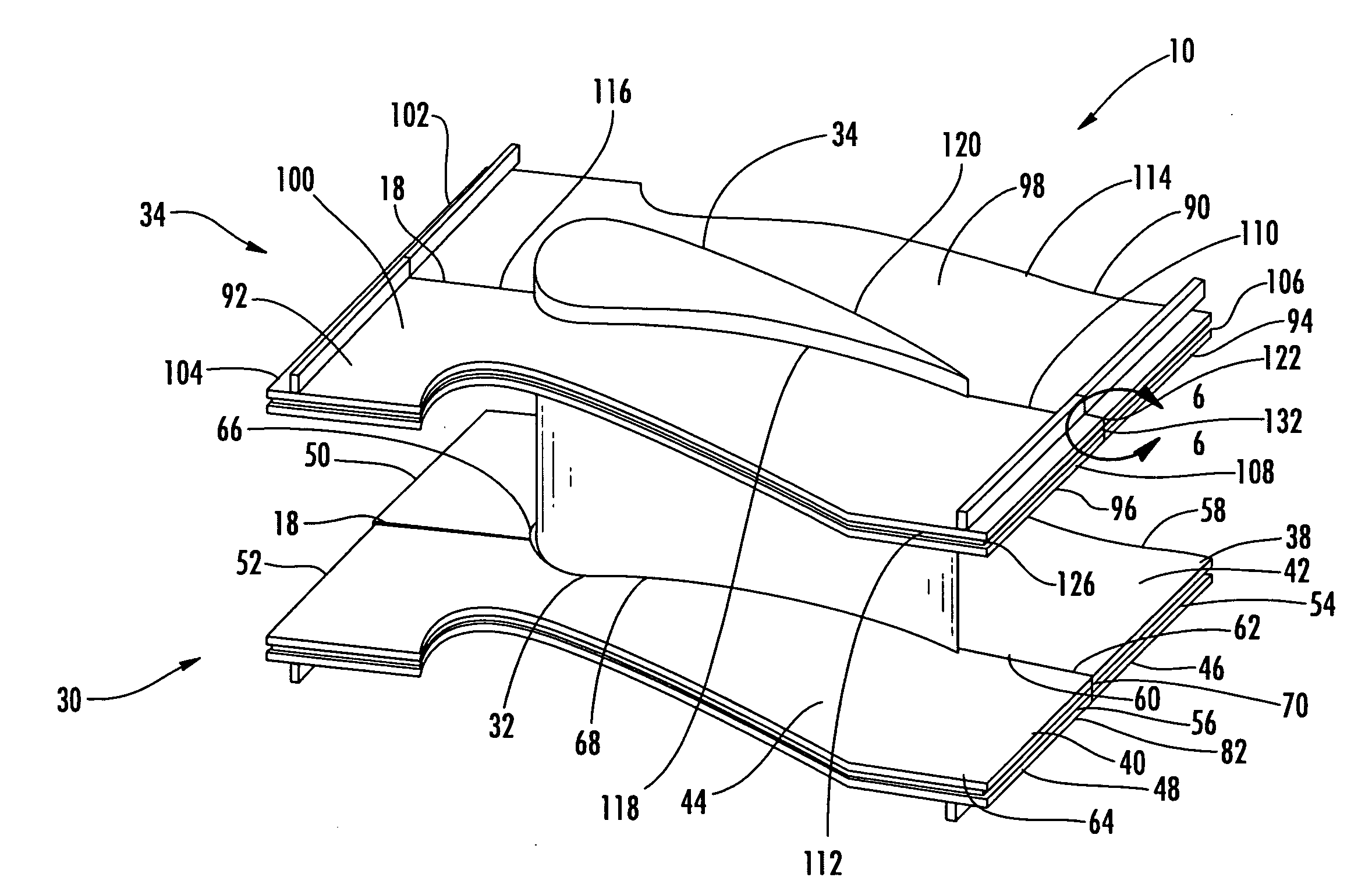
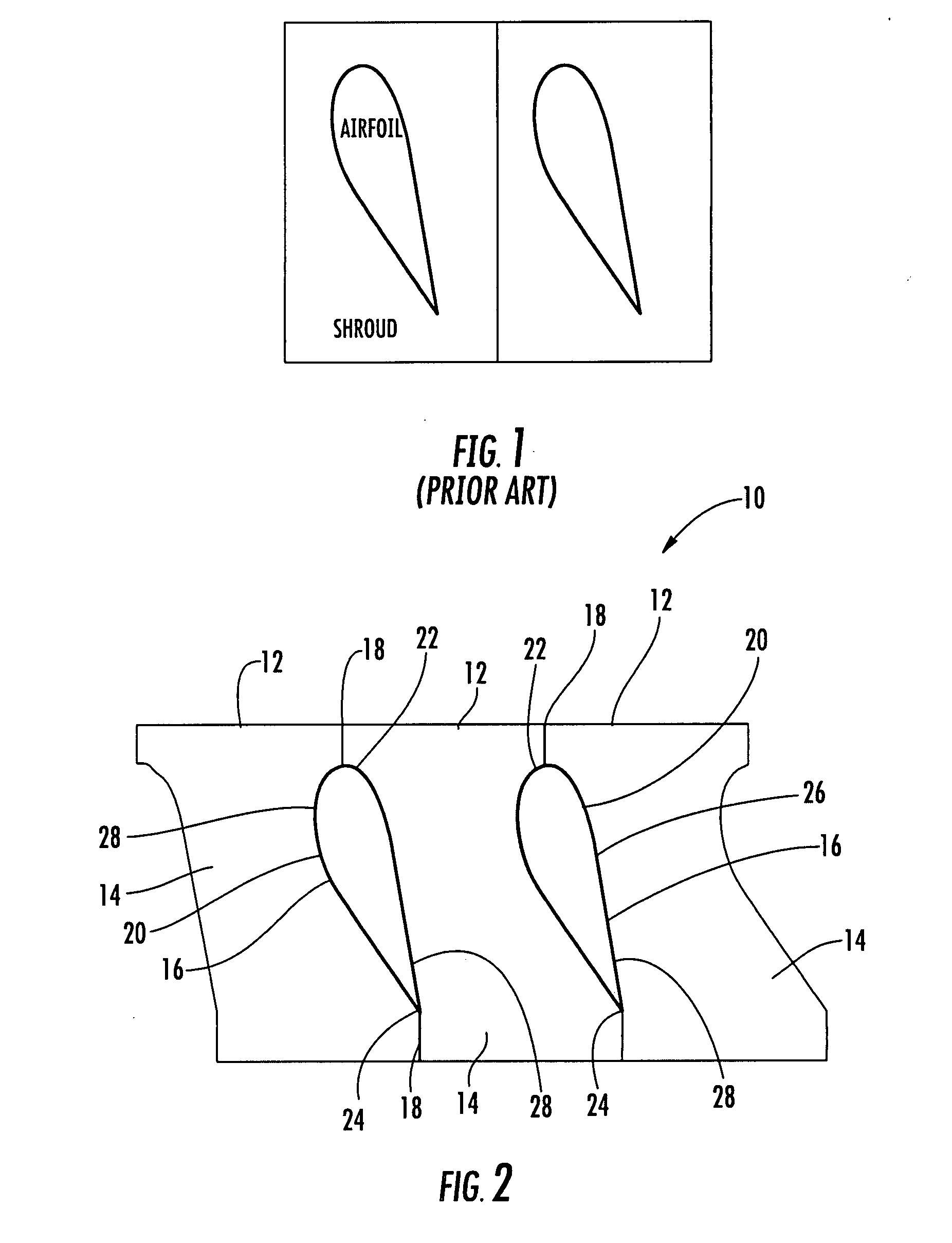
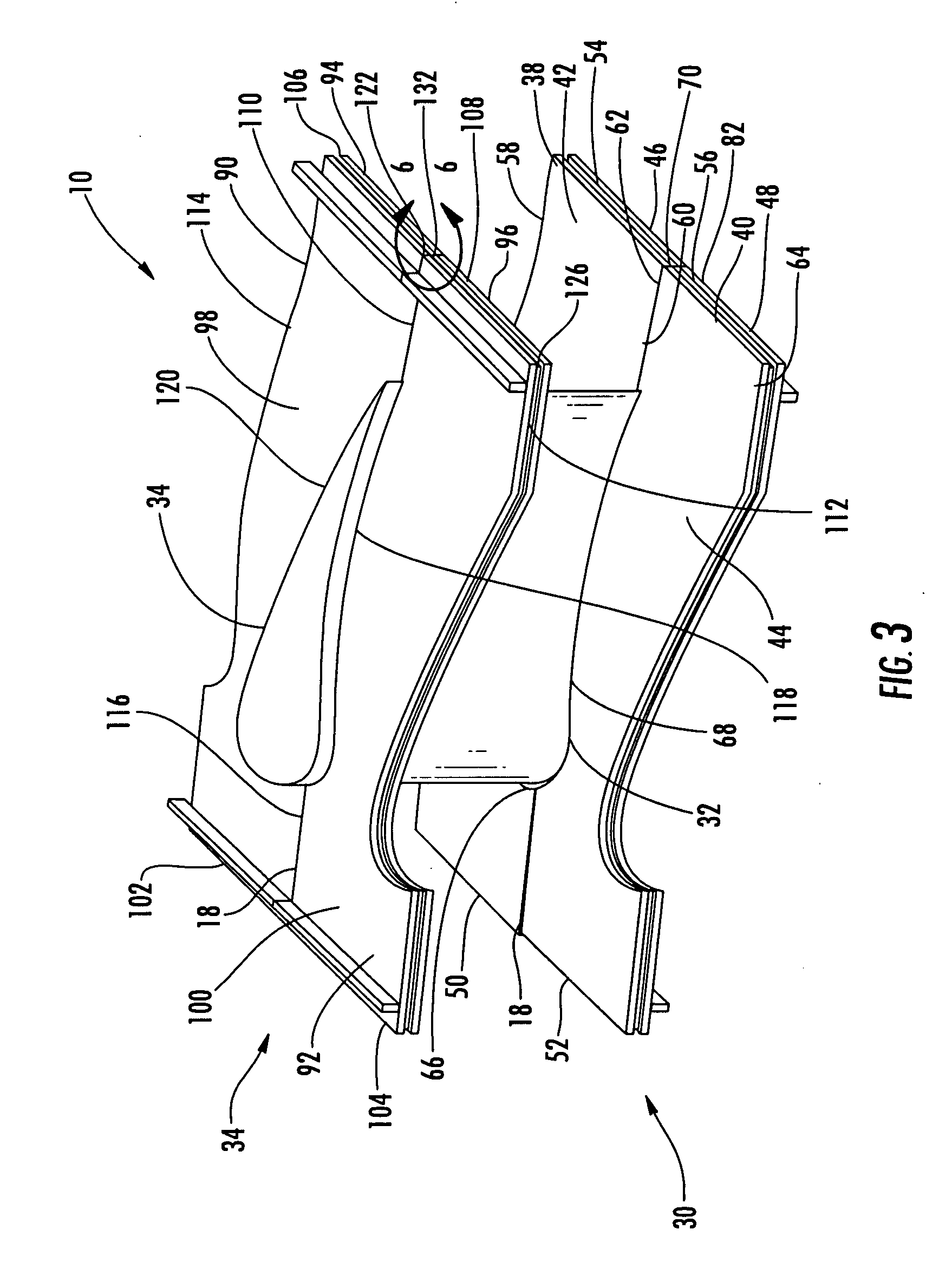
[0028]As shown in FIGS. 2-11, this invention is directed to a turbine vane 10 with endwalls 12 formed from two or more sections 14. The sections 14 may be configured such that the sections 14 form releasable joints 18 with a generally elongated airfoil 16 of the turbine vane 10 at the airfoil 16. The sections 14 may be configured 14 to both support the generally elongated airfoil 16 and to establish cooling fluid flowpaths between the sections 14 and the generally elongated airfoil 16 to cool the aspects of the turbine vane 10 proximate to the intersection of the endwalls 12 and the generally elongated airfoil 16. In addition, the joints 18 between the generally elongated airfoil 16 and the sections 14 may be formed from a connection system that enables forces to be transmitted from the generally elongated airfoil 16 to the endwalls 12 without creating stresses found in conventional turbine vane fillets at the intersection between the generally elongated airfoil 16 and the endwalls ...


PUM


Abstract

A turbine vane with endwalls, wherein at least one endwall is formed from two or more sections configured such that the sections form releasable joints with a generally elongated airfoil of the turbine vane. The sections may be configured to both support the generally elongated airfoil and to establish cooling fluid flowpaths between the sections and the generally elongated airfoil to cool the aspects of the turbine vane proximate to the intersection of the endwalls and the generally elongated airfoil. In addition, the joints between the generally elongated airfoil and the sections may be formed from a connection system that enables forces to be transmitted from the generally elongated airfoil to the endwalls without creating stresses found in conventional turbine vane fillets at the intersection between the generally elongated airfoil and the endwalls.

Description

FIELD OF THE INVENTION[0001]This invention is directed generally to stationary turbine vanes, and more particularly to platforms of turbine vanes.BACKGROUND[0002]Typically, gas turbine engines include a compressor for compressing air, a combustor for mixing the compressed air with fuel and igniting the mixture, and a turbine blade assembly for producing power. Combustors often operate at high temperatures that may exceed 2,500 degrees Fahrenheit. Typical turbine combustor configurations expose turbine vane and blade assemblies to high temperatures. As a result, turbine vanes and blades must be made of materials capable of withstanding such high temperatures, or must include cooling features to enable the component to survive in an environment which exceeds the capability of the material. Turbine engines typically include a plurality of rows of stationary turbine vanes extending radially inward from a shell and include a plurality of rows of rotatable turbine blades attached to a rot...

Claims


Application Information

Patent Timeline
Patent Type & Authority Applications(United States)
IPC IPC(8): F01D5/14
CPCF01D5/147F01D9/02F05D2260/36F05D2240/80
Inventor MARINI, BONNIE D.
Owner SIEMENS ENERGY INC
Why Eureka
Try Eureka