Resonance driven glow plug torch igniter and ignition method

a glow plug torch and ignition method technology, which is applied in the direction of gaseous heating fuel, combustion types, stoves or ranges, etc., can solve the problems of heavy, complex and cumbersome conventional systems, and achieve the effects of high reliability, easy integration into complex assemblies, and easy extensibility

Inactive Publication Date: 2008-12-04
AEROJET ROCKETDYNE OF DE
View PDF87 Cites 17 Cited by
  • Summary
  • Abstract
  • Description
  • Claims
  • Application Information

AI Technical Summary

Benefits of technology

[0005]The present invention therefore provides an uncomplicated, lightweight ignition system that is highly reliable, easy to integrate into complex assemblies, and readily extensible to multiple ignition point applications, such as in a multi-compartment combustor.

Problems solved by technology

These conventional systems, although effective, tend to be relatively complex and heavy as each system requires electrical cabling, connectors, power, and control systems.

Method used


Image

  • Resonance driven glow plug torch igniter and ignition method
  • Resonance driven glow plug torch igniter and ignition method
  • Resonance driven glow plug torch igniter and ignition method

Examples


Embodiment Construction

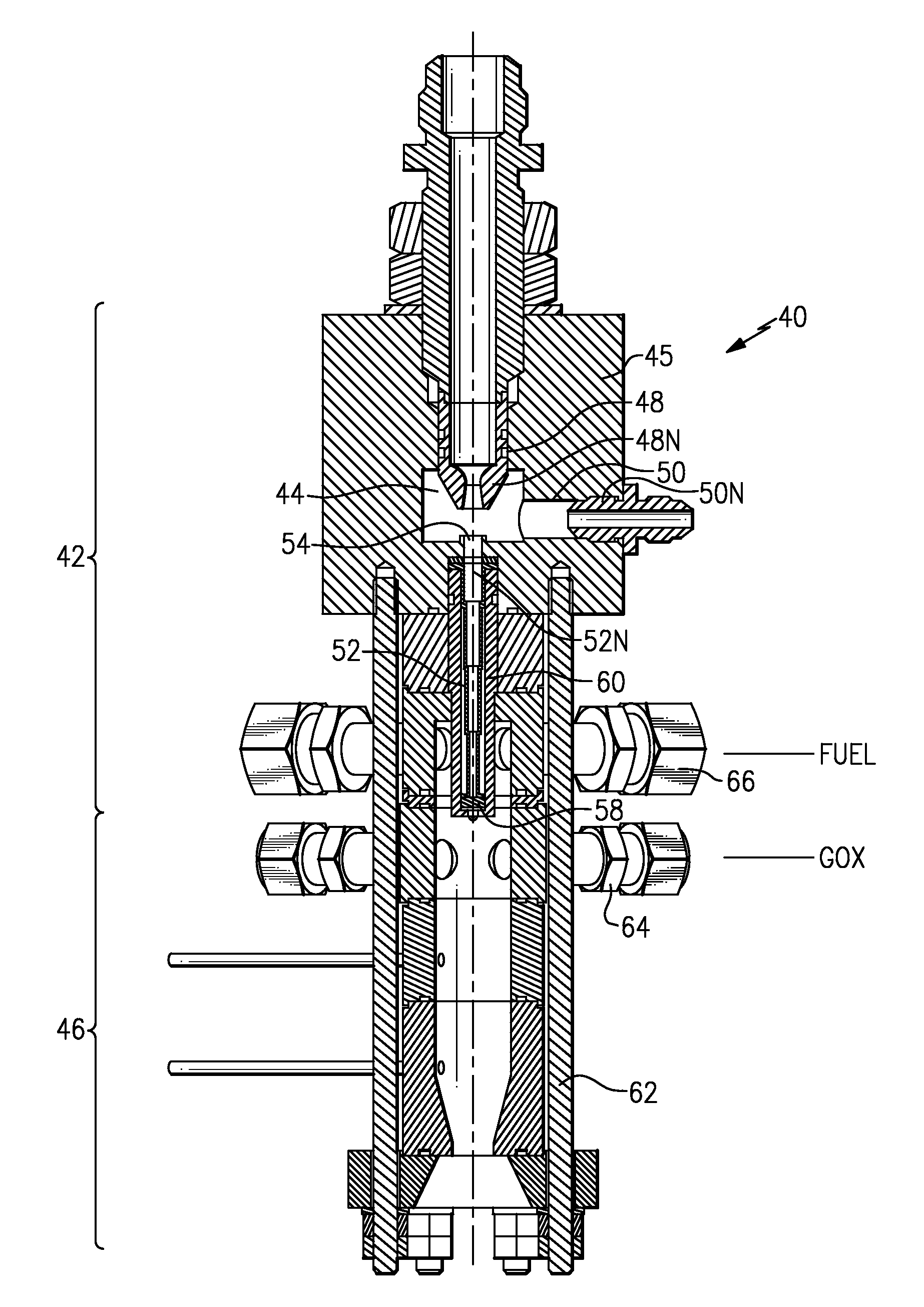
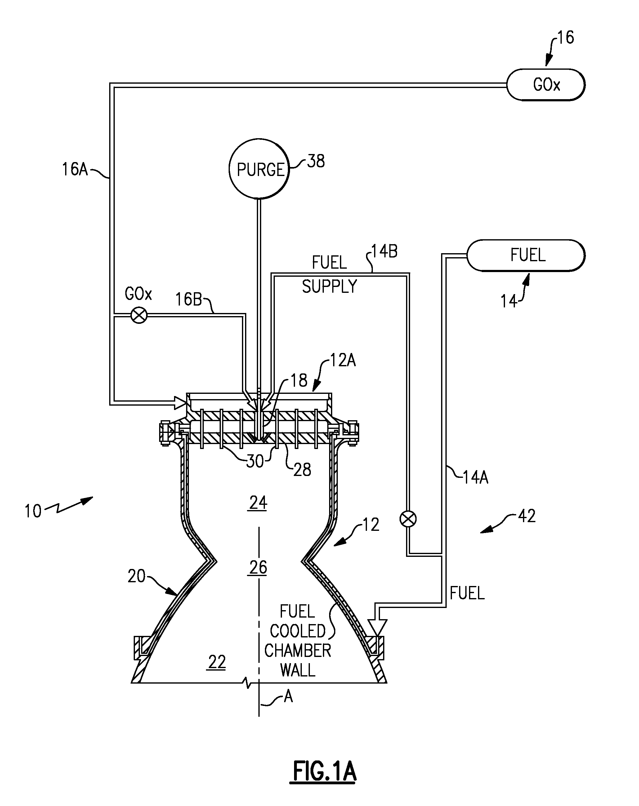
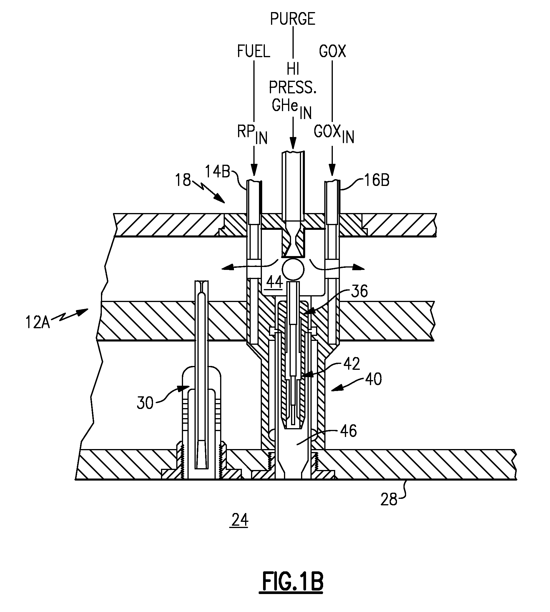
[0013]FIG. 1 illustrates a general schematic view of a combustor 10. A rocket engine combustor is used in this example embodiment. The combustor 10 generally includes a combustion chamber assembly 12, a fuel system 14, an oxidizer system 16 and an ignition system 18. The fuel system 14 and the oxidizer system 16 provide a gaseous ignitable propellant combination to the combustor 10, however, other propellant systems such as liquid will also be usable.

[0014]The combustion chamber assembly 12 is defined by a fluid cooled wall 20 about a center axis A. The fluid cooled wall 20 defines a nozzle section 22, a combustion chamber section 24 upstream of the nozzle section 22, and a combustion chamber throat 26 therebetween. The combustion assembly 12 includes an injector system section 12A with an injector face 28 having a multitude of fuel / oxidizer injector elements 30 (shown somewhat schematically) which receive fuel which passes first through the fuel cooled combustion chamber wall 20 fe...


PUM


Abstract

An ignition system for a combustion device utilizes an oscillating pressure force in a resonance system to generate thermal energy within a resonance driven glow plug. The resonance driven glow plug stores the thermal energy for transfer to ignitable propellant combinations within a torch assembly and thus within the combustion chamber.

Description

BACKGROUND OF THE INVENTION[0001]The present invention relates to an igniter system for ignition of a rocket engine or other combustion device for propulsion, power, or industrial processing applications, and more particularly to a method which utilizes pressure energy to generate thermal energy which is transferred into a glow plug body to store the energy for transfer to ignitable propellant combinations in a torch assembly.[0002]Various conventional ignition systems have been used for ignition of an ignitable propellant mixture in a combustion chamber of a rocket engine. Some ignition systems employ a spark induced by an electrical current. Other ignition systems employ glow plugs which are electrically heated. These conventional systems, although effective, tend to be relatively complex and heavy as each system requires electrical cabling, connectors, power, and control systems.[0003]Accordingly, it is desirable to provide an uncomplicated, lightweight ignition system which is h...

Claims


Application Information

Patent Timeline
Patent Type & Authority Applications(United States)
IPC IPC(8): F23Q1/02F23C15/00
CPCF02C7/264F02K9/95F05D2260/99F23N2027/00F23N2027/04F23R3/002F24C3/14F23N2227/00F23N2227/04
Inventor HORN, MARK DAVID
Owner AEROJET ROCKETDYNE OF DE
Why Eureka
Try Eureka