Shoulder rehabilitation and exercise device

Active Publication Date: 2008-12-04
BINNS MATTHEW +2
View PDF21 Cites 8 Cited by
  • Summary
  • Abstract
  • Description
  • Claims
  • Application Information

AI Technical Summary

Benefits of technology

[0044]After the device has been adjusted as described above, the user may then inwardly and outwardly rotate the actuator arm by applying a corresponding inward and outward lateral force thereto via the handgrip. A user may increase the resistance (and thus exercise difficulty) provided by the device to such motion by simply increasing the force he or she applies to the actuator arm via the hand grip. The increased force tends to cause the arcuate motion of the actuator and restrictor arm to accelerate. This acceleration in movement is transferred to the hydraulic damper via the central axis. More specifically, increased speed of rotation of the central damper necessarily causes an increase in rotation of the central axle which, in turn, cause an increase in the velocity of hydraulic fluid propelled by a fluid propulsion means such as, for example, piston(s), vane(s) or fin(s). This increased speed forces an increased volume of fluid through the apertures of a hydraulic fluid flow valve (also referred to herein as hydraulic flow valve and flow valve) The effect of the forcing of the increased volume of fluid through the aperture is, of course, increased resistance to flow and, accordingly, the hydraulic piston(s), vane(s) or fin(s) provide more resistance to the rotation of the central axle which, in turn, is transmits such increased resistance to the restrictor and actuator arm.
[0045]In certain preferred embodiments of the present invention, the hydraulic damper includes a resistance adjustment wheel which controls an adjustable hydraulic flow valve. A user may turn the adjustment wheel to a selected position indicated by, for example, a number on the wheel which is aligned with a mark adjacent the damper. Movement of the wheel varies the aperture of an adjustable hydraulic fluid flow valve. More specifically, turning the wheel in one direction has the effect of increasing the aperture of the valve. An increase in flow valve aperture causes, as is well known to the art of hydraulic fluid dynamics, a reduction in resistance to flow. This reduction in flow resistance, in turn, results in a decrease resistance of the hydraulic damper to rotation via inward and outward rotation of the actuator arm. Conversely, turning the resistance adjustment wheel in the other direction has the effect of decreasing the aperture of the hydraulic fluid flow valve, which increases the resistance presented by the valve to hydraulic fluid flow. Such increased valve resistance, in turn, increases the resistance to movement of the damper piston(s), vane(s) or fin(s0 and thus increased resistance presented by the damper to the restrictor and actuator arm via the central axle. Thus, rotation of the resistance adjustment wheel in one direction increases resistance to user inward and outward rotation of the actuator arm while rotation of the resistance adjustment wheel in the opposite direction decreases such resistance. However, regardless of the adjustment wheel setting, increased lateral force applied to the hand grip of the device by a user attempting to perform internal and/or external shoulder rotations will, of course, increase resistance to such movement generated by the hydraulic damper due to well known principles of hydraulic dynamics. Conversely, a user's reduction in force applied to the hand grip will result in a decrease in hydraulic damper resistance to movement.
[0046]The device of the present invention is designed and configured to enable a user to utilize the device by placing the forearm corresponding to the shoulder to be exercised upon an actuating arm while the elbow of that same arm is retained in an

Problems solved by technology

However, due largely to its high flexibility, the shoulder is frequently subject to injury leading to pain, inflamation and loss of motion.
Each of the muscles of the rotator cuff are susceptible to injury such as sprains and muscle tears which can be debilitating.
The supraspinatus muscle and tendon is especially susceptible to such injury and is the most commonly injured part of the rotator cuff due, in large part, to its position and path of contraction.
However, any of these muscles and associated tendons can an are involved in rotator cuff injuries.
Utilizing free weight exercise was of limited value in that, depending upon the user's position, it is difficult to obtain consistent resistance through, for example, a complete 180 degrees of internal or external rotation.
A handheld weight, following an arch-like movement, will not provide consistent resistance.
Such techniques also make no allowance for control and achievement of a safe range of motion.
Holding a free weight by hand, especially in regard to a rehabilitation exercise, may be dangerous in that the potential energy associated with the weight might cause a user to over-extend his or her movements—go beyond a range of motion in which such movement is safe—.
Also, if a user should suffer a spasm, sudden pain or lose consciousness, the potential ene

Method used


Image

  • Shoulder rehabilitation and exercise device
  • Shoulder rehabilitation and exercise device
  • Shoulder rehabilitation and exercise device

Examples


Example

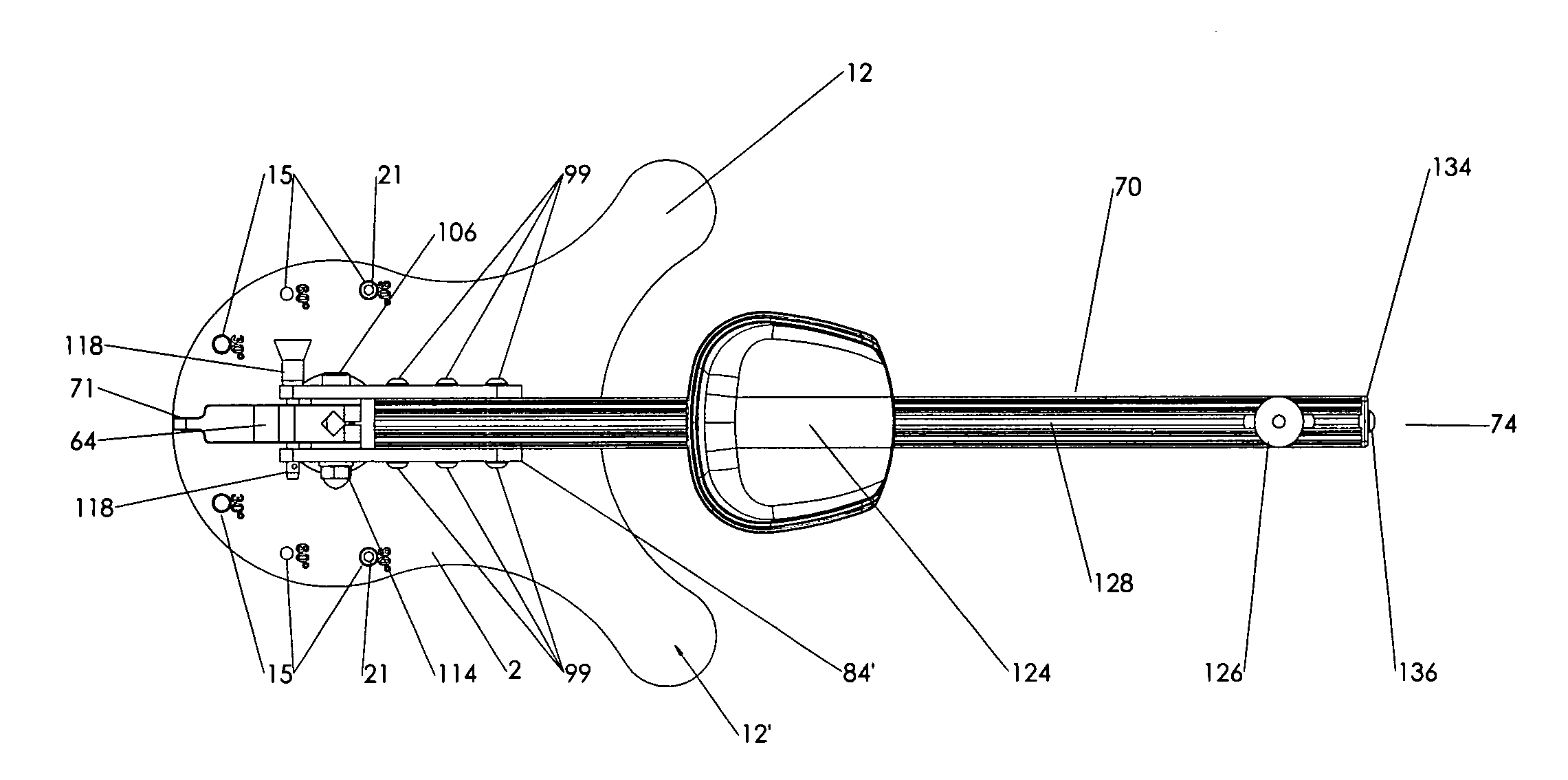
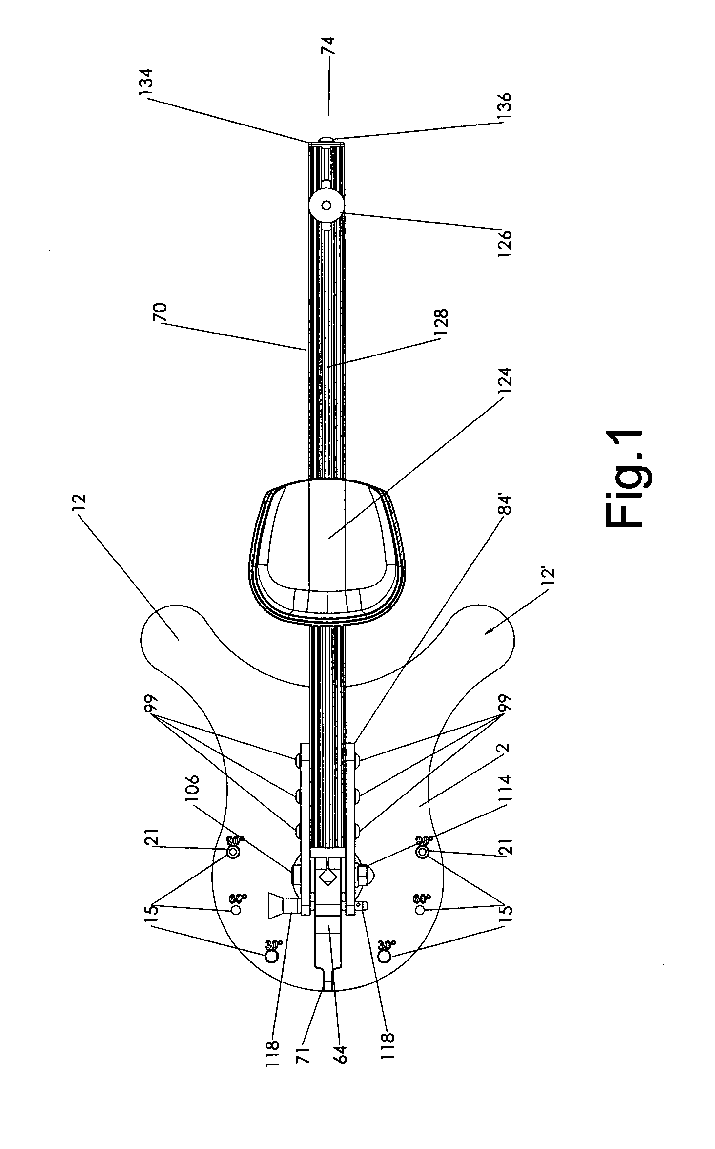
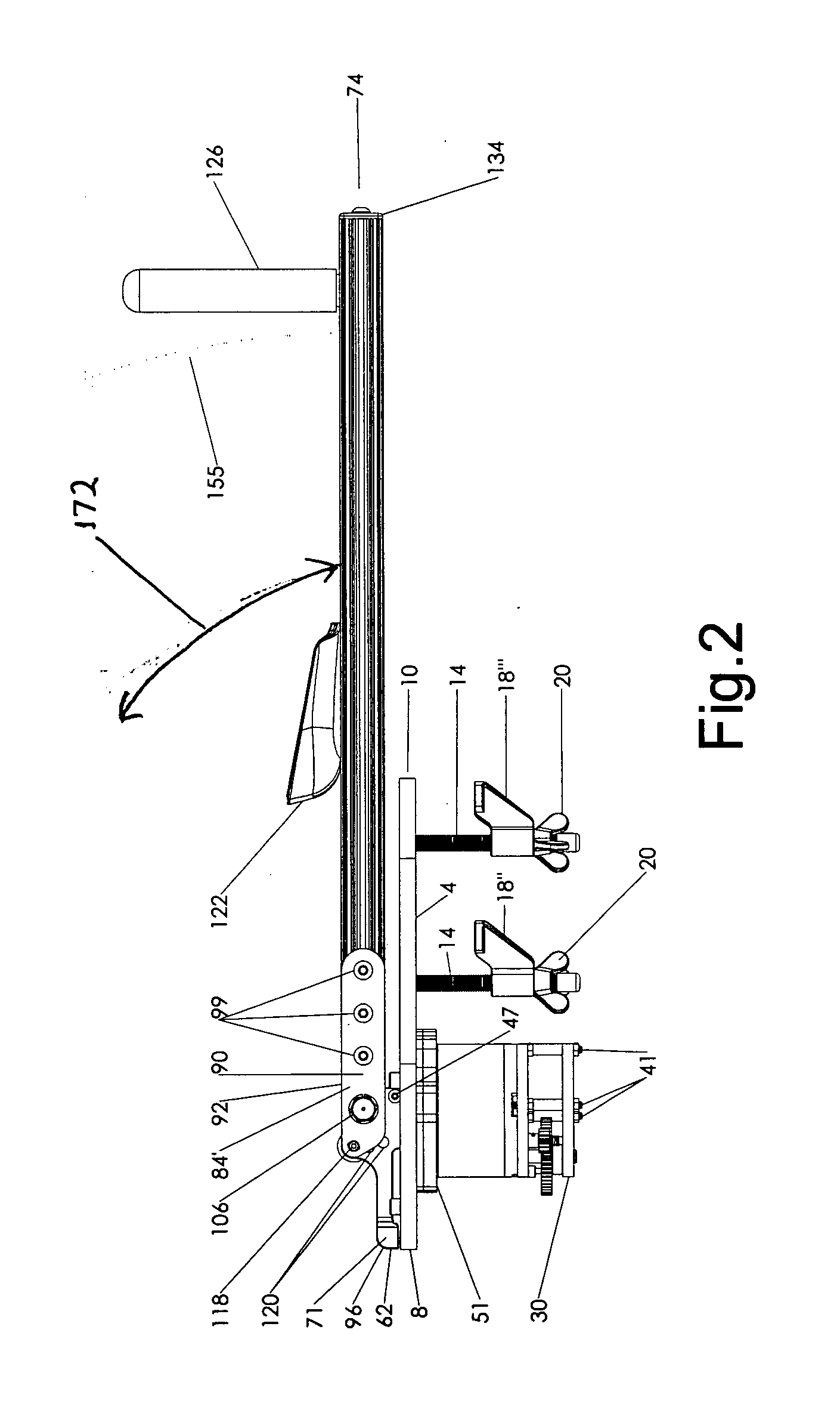
[0060]The drawing figures (1-8) illustrate a preferred embodiment of the shoulder therapeutic and exercise device of the present invention. FIGS. 9 and 10 illustrate, in detail, the damper shown in the preceding figures.

[0061]As illustrated in the figures, base plate 2 is configured as a flat plate having a lower surface 4 and an upper surface 6. The base plate may also be described as having a proximal portion 8 and a distal portion 10 as well as a longitudinal axis running from the proximal to distal portions of the base plate, along the midline thereof. The overall shape of the base plate utilized in the preferred embodiment illustrated in the figures includes two distal extensions 12&12′. As discussed in more detail below, these distal extension of the distal portion of the base plate of this particular embodiment of the present invention enable the base plate to easily engage the corner portion of a table top. The base plate illustrated also includes restrictor bores 15, which,...


PUM


Abstract

A shoulder rehabilitation and exercise device is disclosed which enables a user to perform internal and external rotations of both right and left shoulder. The device is comprised of a base plate, hydraulic damper, restrictor arm, actuator arm, elbow cup and hand grip. A smooth, fluid-like movement is achieved during performance of arcuate internal and external shoulder rotations while also providing automatic increases and decreases in resistance to such motion in response to user effort. In certain preferred embodiments, in addition to such automatic adjustment of resistance, the device includes a means of manually adjusting resistance. The device may be utilized to perform the aforementioned internal and external rotations on a user's right or left side without need for making any adjustments to the machine. Range of motion limitations may be set to control the arcuate degree of internal and external rotations performed. Adjustment in the elevation of a user's forearm via adjustment of the actuator arm is provided. The actuator arm includes an adjustable elbow cup and adjustable hand grip. The device does not store potential energy or produce sufficient momentum to oppose a user's immediate and safe termination of motion.

Description

RELATED APPLICATIONS [0001]This application claims the benefit of U.S. Provisional Application No. 60941168 filed on May 31, 2007.TECHNICAL FIELD [0002]The present invention relates to the field of rehabilitation and exercise equipment. More specifically, a rehabilitation and exercise device is disclosed herein specifically adapted and configured to enable a user to strengthen and increase the range of motion of muscles associated with internal and external rotation of the shoulder.BACKGROUND OF THE ART[0003]The shoulder joint is the most mobile and flexible joint in the human body. This joint controls the position of the upper arm and, due to the high flexibility of the joint, enables a tremendous range of motion. However, due largely to its high flexibility, the shoulder is frequently subject to injury leading to pain, inflamation and loss of motion. The humerus and the scapula are the two major components of the shoulder joint with a portion of the head of the humerus functioning...

Claims


Application Information

Patent Timeline
IPC IPC(8): A61H1/00
CPCA61H1/0281Y10S482/904
Inventor BINNS, MATTHEWPROTAS, EUGENE DAVIDAVENARIUS, SCOTT
Owner BINNS MATTHEW
Why Eureka
Try Eureka