Spine surgery method and instrumentation

a spine surgery and instrumentation technology, applied in the direction of prosthesis, osteosynthesis device, bumper, etc., can solve the problems of reducing surgeon visualization of the surgical site, affecting the surgical effect of the surgeon, and the limitations of the known spinal surgical method, so as to facilitate and secure the connection, facilitate the adjustment of the positioning of the interbody implant, and facilitate the effect of relative movemen

Active Publication Date: 2008-12-04
VERTEBRATION
View PDF48 Cites 70 Cited by
  • Summary
  • Abstract
  • Description
  • Claims
  • Application Information

AI Technical Summary

Benefits of technology

[0026]Another advantage of this invention is that the implant may be relatively easily and securely attached to the inserter and then detached from the inserter.
[0027]Still another advantage of this invention is that the distractor and inserter may easily move relative to each other along a distractor / inserter rail / groove interconnection to insert the implant.
[0028]Another advantage of this invention is that the surgeon may make consistent and reproducible biplanar, midline placement of the interbody implant.
[0029]Another advantage of this invention, according to one embodiment, is that the surgeon may easily make adjustments in positioning the interbody implant because of the centralized placement of the distractor and its possible motion with the inserter and interbody implant as a single moveable unit until surgeon preference dictates disengagement.
[0030]Another advantage of this invention is that the surgical instrumentation allows for minimally invasive deployment via either an anterior, anterolateral, posterior or posterolateral approach, with the latter approach possible via either a transforaminal or extraforaminal approach.
[0031]Yet another advantage of this invention, according to one embodiment, is that the centralized distraction instrument is functionally integrated with the implant and the inserter. This permits measured and controlled placement of the interbody implant.

Problems solved by technology

As a result, known spinal surgical methods, instrumentation and interbody implants have limitations.
One limitation is that the physical components are relatively large and bulky.
This reduces surgeon visualization of the surgical site.
Another limitation of known spinal surgical methods is that known surgical tools and implants are cumbersome and difficult to maneuver within the limited surgical space available.
The limitations of current instrumentation in MIS spine surgery are noted particularly with regards to interbody fusion surgery.

Method used


Image

  • Spine surgery method and instrumentation
  • Spine surgery method and instrumentation
  • Spine surgery method and instrumentation

Examples


Embodiment Construction

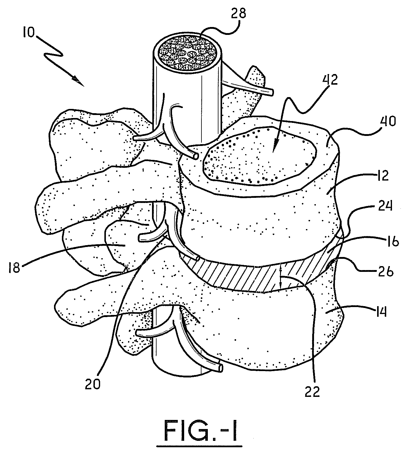
[0054]Referring now to the drawings wherein the showings are for purposes of illustrating embodiments of the invention only and not for purposes of limiting the same, FIG. 1 shows a portion of a spinal column, a spinal segment 10 that may use the surgical instrumentation 300 of this invention to insert an implant 100, as illustrated in FIGS. 2-5. The particular implant can be any implant chosen with sound engineering judgment. The implant 100 may be, for non-limiting examples, any of the implants described in commonly owned U.S. patent application Ser. No. 11 / 236,068, publication number US 2007 / 0073398 A1, published on Mar. 29, 2007, titled SPINE SURGERY METHOD AND IMPLANT, which is incorporated herein by reference. The spinal segment 10 is made up of two vertebrae 12, 14 attached together by ligaments with a disc 16 separating them. Facet joints 18 fit between the two vertebrae 12, 14 and allow for movement. The neural foramen 20 between the vertebrae 12, 14 allow space for the ner...


PUM

PropertyMeasurementUnit
angleaaaaaaaaaa
lengthaaaaaaaaaa
height H1aaaaaaaaaa

Abstract

Surgical instrumentation for use in placing an implant into a disc space between a pair of spinal vertebrae may include: (a) a distractor having a distal end that may be placed into the disc space between the pair of spinal vertebrae; (b) an inserter for use in moving the implant toward the disc space between the pair of spinal vertebrae; and, (c) a distractor/inserter rail/groove interconnection that interconnects the distractor and the inserter for relative movement thereby.

Description

I. BACKGROUND OF THE INVENTION[0001]A. Field of Invention[0002]This invention pertains to the art of methods and apparatuses regarding spine surgery and more specifically relates to surgical procedures and associated instrumentation used to position an implant within an intradiscal space between two adjacent vertebral bodies.[0003]B. Description of the Related Art[0004]The volume of spinal surgeries to treat degenerative disc and facet disease has steadily increased over the past decade, fueled by population demographics and advancements in diagnostic and instrumentation adjuncts. Improvements in intraoperative radiological imaging and surgical technique have generated a great deal of interest in applying minimally invasive surgical (MIS) techniques to spinal applications. As in other surgical subspecialties, it is hoped such minimally invasive techniques applied to spinal surgery will result in less soft tissue trauma, less operative blood loss, reduced operative time, faster recov...

Claims


Application Information

Patent Timeline
Patent Type & Authority Applications(United States)
IPC IPC(8): A61B17/58A61B17/00
CPCA61B17/025A61B2017/0256A61F2/4425A61F2/4455A61F2/4611A61F2002/30179A61F2230/0058A61F2002/30462A61F2002/30471A61F2002/4415A61F2220/0025A61F2220/0075A61F2220/0091A61F2002/30387Y10T29/49826B60K13/02B60K13/04B60Q1/2626B60Q1/2653B60R19/18B60R19/50B60R2019/1886
Inventor FABIAN, HENRY F.CICORETTI, LARRY A.
Owner VERTEBRATION
Why Eureka
Try Eureka