Eureka AIR delivers breakthrough ideas for toughest innovation challenges, trusted by R&D personnel around the world.

Intake air mass flow measurement device

a mass air flow and measurement device technology, applied in liquid/fluent solid measurement, instruments, machines/engines, etc., can solve the problem of extremely low water film extendability over the entire circumference, and achieve the effect of reducing the number of components, reducing the amount of characteristics change, and saving natural resources

Active Publication Date: 2008-12-11
HITACHI ASTEMO LTD
View PDF12 Cites 18 Cited by
  • Summary
  • Abstract
  • Description
  • Claims
  • Application Information

AI Technical Summary

Benefits of technology

[0016]Moreover, the pressure intake port formed in a mass air flow meter body is preferably constructed such that an intake passage thereof formed by a tube passage is preliminarily opened to a recess provided in an outer wall of the intake air mass flow measurement device body. This is to prevent dust or the like from easily adhering onto the outer wall of the mass air flow meter body and to thus prevent the adhering dust from disturbing the pressure intake process.
[0019]Today, the world faces environmental problems such as global warming. In this regard, the present invention can contribute to saving natural resources by decreasing the number of components of the combustion control device. Moreover, to cope with exhaust gas control, it is necessary to be able to maintain high-precision fuel control for a long period of time. By doing this, it becomes possible to decrease the amount of characteristics change with age in the heating resistor type mass air flow measurement device and the pressure sensing device. With this construction, it is possible to provide an engine control system that is eco-friendly and fuel-efficient and discharges cleaner exhaust gas.

Problems solved by technology

The possibility of occurrence of a water film in the gap is basically the same as the conventional pressure intake tube; however, the possibility that the water film extends over the entire circumference is extremely low.

Method used


Image

  • Intake air mass flow measurement device
  • Intake air mass flow measurement device
  • Intake air mass flow measurement device

Examples


embodiment 1

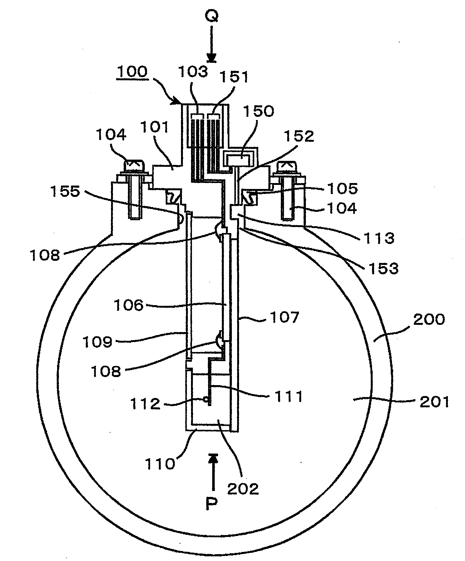
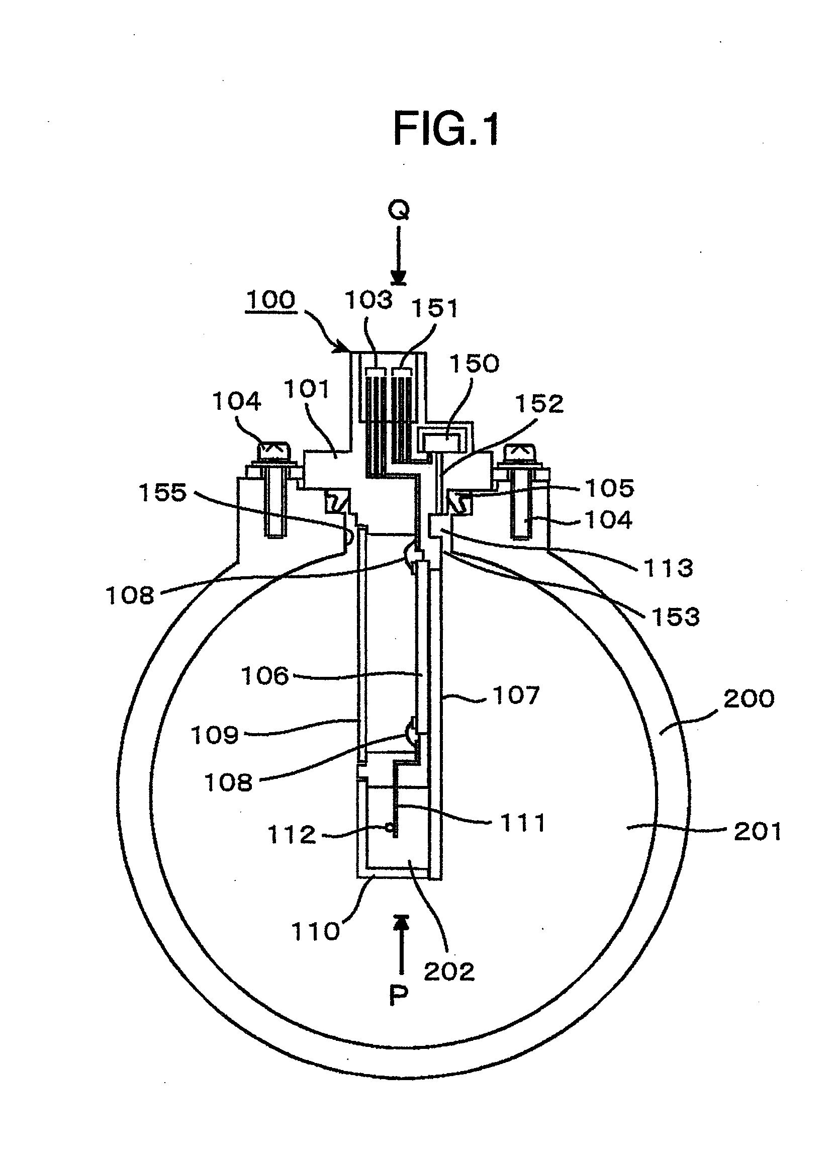
[0036]A specific construction example of the present invention will be described with reference to FIG. 1.

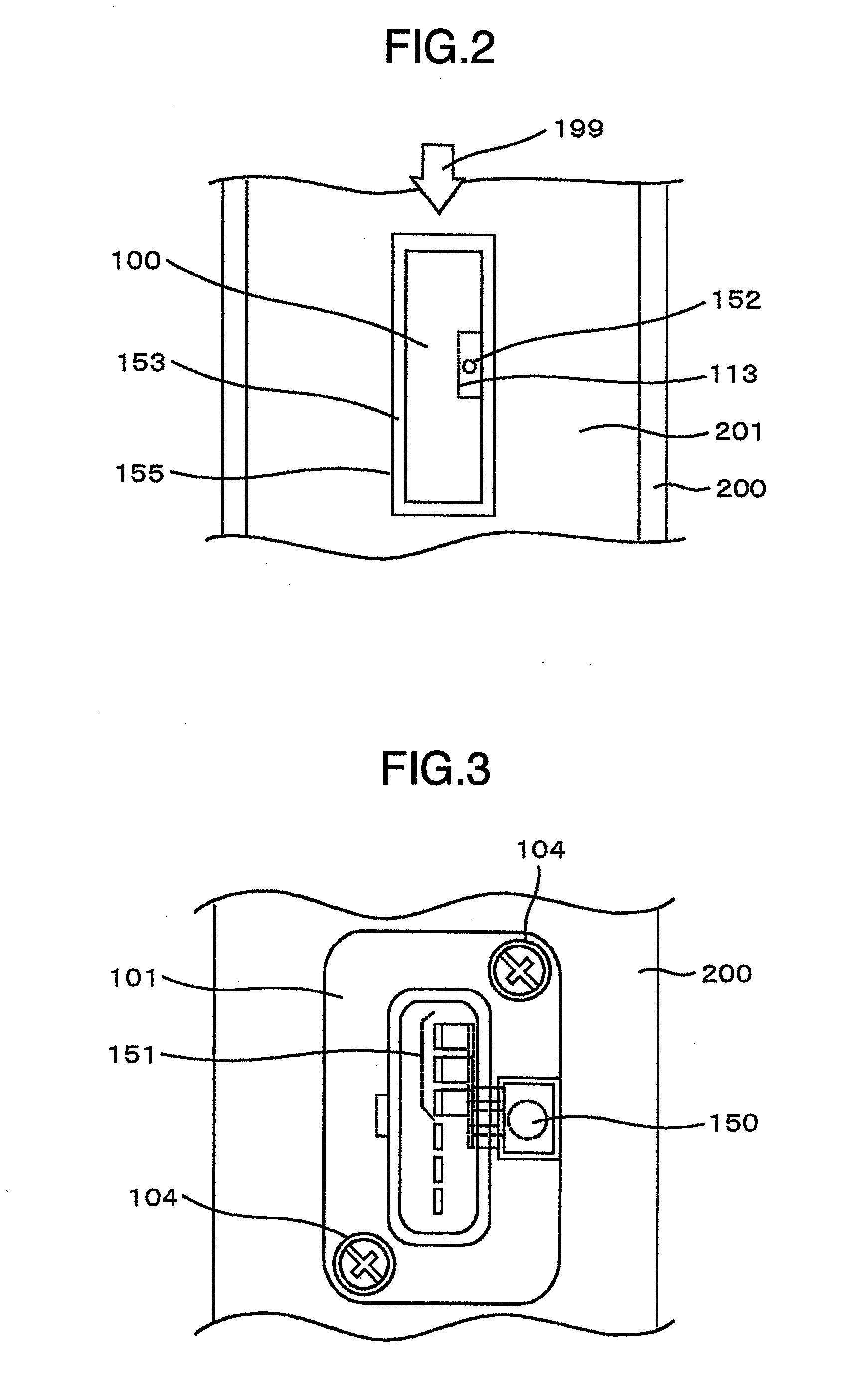
[0037]An insertion port 155 (see FIG. 2) into which a part of the heating resistor type mass air flow measurement device 100 is inserted is formed in a part of a main air flow passage constituting member (intake air tube constituting member) 200, which forms a main air flow passage (hereinafter, referred to as intake air tube passage, or simply, intake air tube) 201, in which the heating resistor type mass air flow measurement device 100 including the pressure sensing part 150 integrally is provided. The attachment is performed by fixing the housing constituting member 101 which forms a case member of the heating resistor type mass air flow measurement device 100, to the intake air tube passage constituting member 200 by a screw 104.

[0038]The heating resistor type mass air flow measurement device 100 includes, in addition to the housing constituting member 101, a base member 107...


PUM


Abstract

In an intake air mass flow measurement device, for preventing clogging in a pressure intake tube due to water or the like entering the pressure intake tube in a device measuring a pressure in the intake air tube, the intake air mass flow measurement device includes a mass air flow measurement device for measuring an intake air mass flow in an intake air tube; and a pressure sensing device for sensing pressure in the intake air tube, the pressure sensing device being integrated with the mass air flow measurement device, and an aperture plane opened to the inside of a main air flow passage for detection of the pressure takes in pressure by using a gap generated between a main air flow passage constituting member and an insertion part of the mass air flow measurement device when a measurement part of the mass air flow measurement device is inserted into the main air flow passage. With this construction, it is possible to provide a structure in which water or the like can hardly clog the pressure intake port.

Description

FIELD OF THE INVENTION[0001]The present invention relates to a heating resistor type mass air flow measurement device which is suitable for measurement of intake air mass flow in an internal combustion engine and to an internal combustion control device using the same.DESCRIPTION OF RELATED ART[0002]As a mass flow measurement technology for an internal combustion engine, a heating resistor type mass air flow measurement device is known (see JP-B2-3523022 for reference). This device takes advantage of the fact that the amount of heat that a heating resistor is deprived of is in correlation with the amount of intake air flow and is capable of directly measuring the mass air flow needed by the combustion control of an engine, and is therefore widely used, particularly, as a flow meter for air fuel ratio control in an automobile.[0003]Moreover, as a pressure sensing device for detecting pressure in an intake air tube, a type of the device disclosed in JP-A-2006-292391 is generally used ...

Claims


Application Information

Patent Timeline
IPC IPC(8): G01M15/00
CPCG01F1/40G01F1/684G01F5/00
Inventor SAITO, TAKAYUKIIGARASHI, SHINYAYOGO, TAKAYUKIKOBAYASHI, CHIHIRO
Owner HITACHI ASTEMO LTD
Why Eureka
Eureka Blog
Learn More