Silicon-Based Light Emitting Diode for Enhancing Light Extraction Efficiency and Method of Fabricating the Same

Inactive Publication Date: 2008-12-11
ELECTRONICS & TELECOMM RES INST
View PDF6 Cites 52 Cited by
  • Summary
  • Abstract
  • Description
  • Claims
  • Application Information

AI Technical Summary

Benefits of technology

[0015]Since a silicon-based light emitting diode according to the present invention is fabricated using a silicon-based semiconductor, not a compound semiconductor, the fabrication cost is low. In addition, the silicon-based light emitting diode according to the present invention can be fabricated using CMOS technologies and can be efficiently integrated.
[0016]A silicon-based light emitting diode according to the present invention has a surface structure with a micron-scale pattern that can enhance the light extraction efficiency according to geometric optics on the emitting layer. The surface structure can be formed by forming a surface pattern on the upper electrode layer or by dry-etching the upper electr

Problems solved by technology

Such light emitting diodes using compound semiconductors are incompatible with other photoelectric devices using silicon-based semiconductors.
However, due to the indirect transition characteristic of silicon semiconductors, the light extraction efficie

Method used


Image

  • Silicon-Based Light Emitting Diode for Enhancing Light Extraction Efficiency and Method of Fabricating the Same
  • Silicon-Based Light Emitting Diode for Enhancing Light Extraction Efficiency and Method of Fabricating the Same
  • Silicon-Based Light Emitting Diode for Enhancing Light Extraction Efficiency and Method of Fabricating the Same

Examples


Embodiment Construction

[0031]The present invention will now be described more fully with reference to the accompanying drawings, in which exemplary embodiments of the invention are shown. The invention may, however, be embodied in many different forms and should not be construed as being limited to the embodiments set forth herein; rather, these embodiments are provided so that this disclosure will be thorough and complete, and will fully convey the concept of the invention to those skilled in the art. In the drawings, the thicknesses of layers and regions are exaggerated for clarity. It will also be understood that when a layer is referred to as being ‘on’ another layer or substrate, it can be directly on the other layer or substrate, or intervening layers may also be present. Like reference numerals in the drawings denote like elements, and thus their description will be omitted.

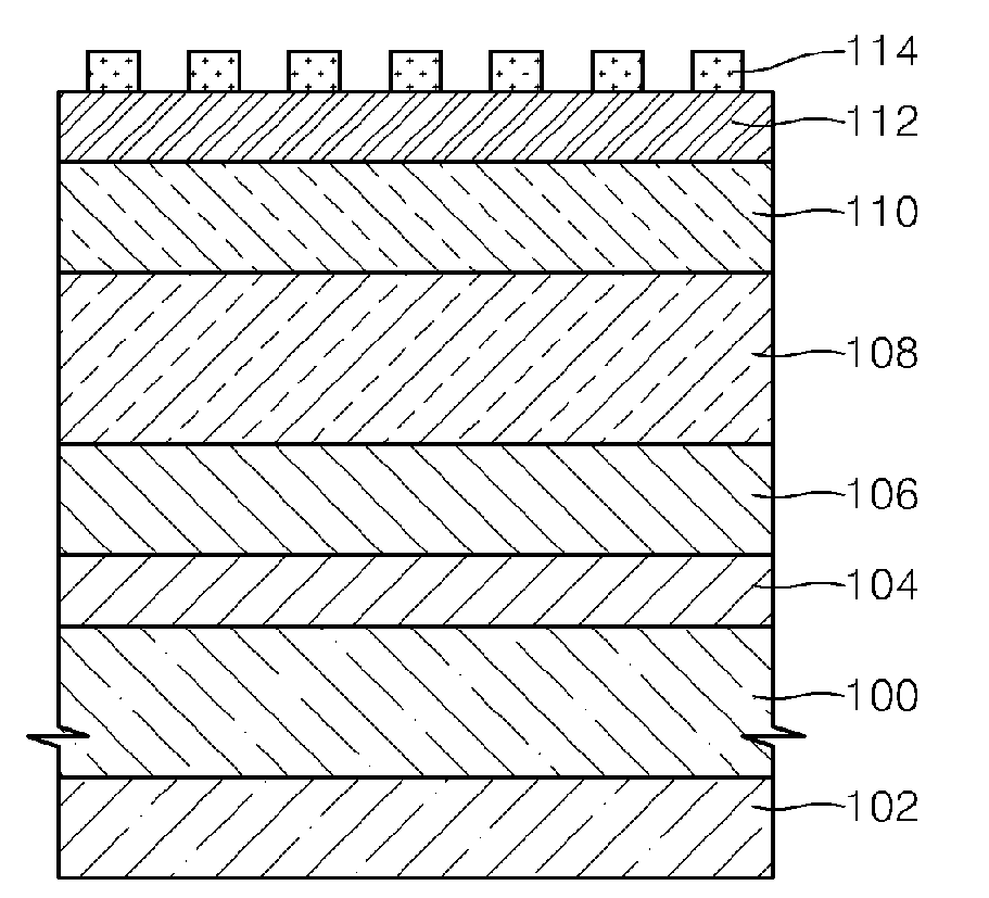
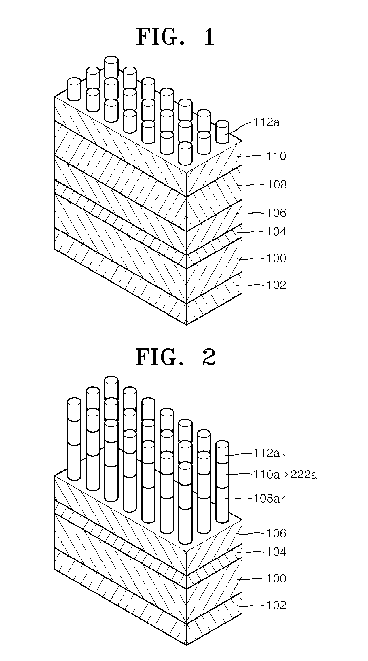
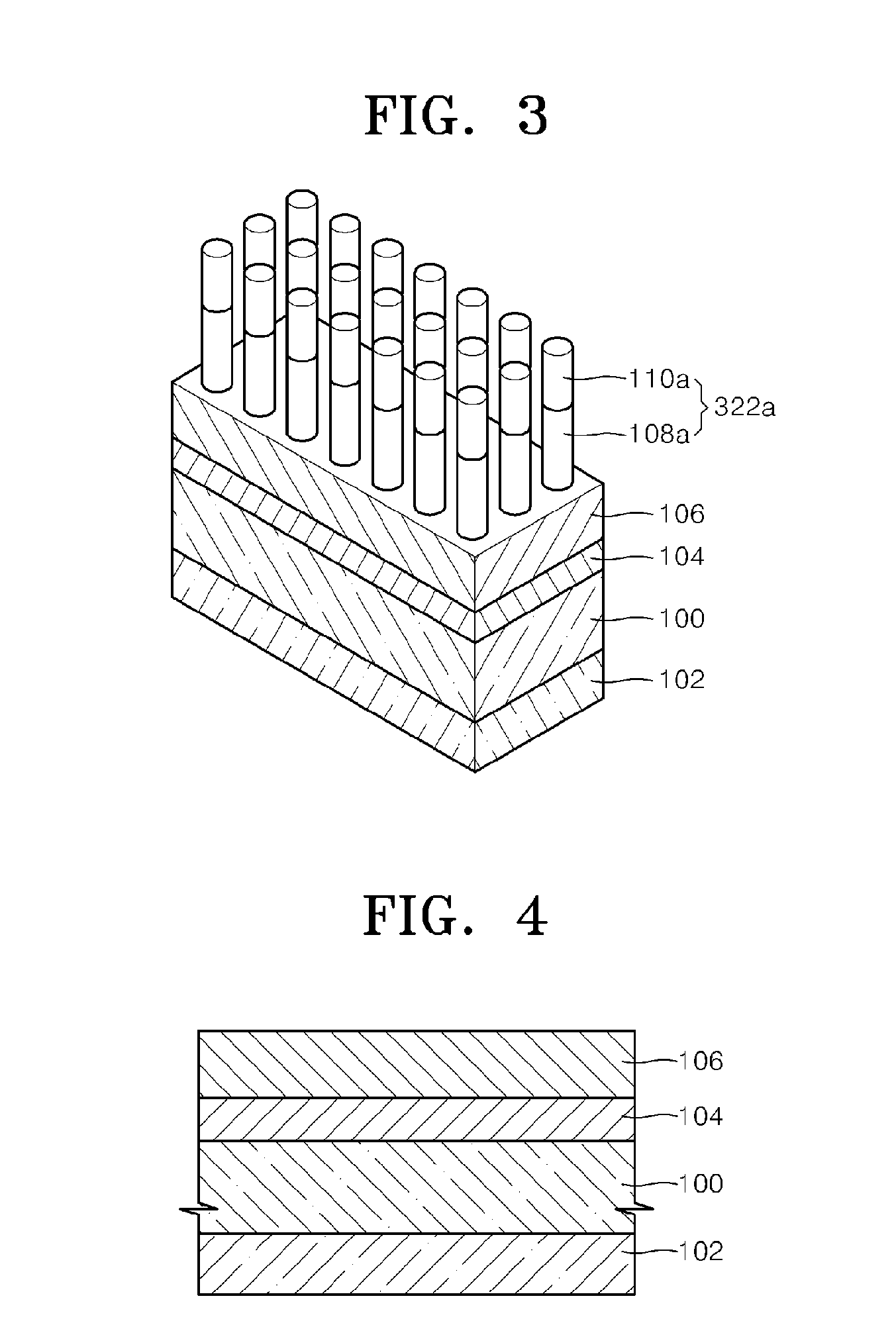
[0032]FIG. 1 is a perspective view illustrating a structure of a silicon-based light emitting diode according to an embodiment...


PUM


Abstract

Due to the indirect transition characteristic of silicon semiconductors, the light extraction efficiency of a silicon-based light emitting diode is lower than that of a compound semiconductor-based light emitting diode. For this reason, there are difficulties in practically using and commercializing silicon-based light emitting diodes developed so far. Provided is a silicon-based light emitting including: a substrate with a lower electrode layer on a lower surface thereof; a lower doped layer that is formed on an upper surface of the substrate and supplies carriers to an emitting layer; the emitting layer that is a silicon semiconductor layer including silicon quantum dots or nanodots formed on the lower doped layer and has a light-emitting characteristic; an upper doped layer that is formed on the emitting layer and supplies carriers to the emitting layer; an upper electrode layer formed on the upper doped layer; and a surface structure including a surface pattern formed on the upper electrode layer, a surface structure including an upper electrode pattern and an upper doped pattern formed by patterning the upper electrode layer and the upper doped layer, or a surface structure including the surface pattern, the upper electrode pattern, and upper doped pattern, wherein the surface structure enhances the light extraction efficiency of light emitted from the emitting layer according to geometric optics.

Description

TECHNICAL FIELD[0001]The present invention relates to a light emitting diode and a method of fabricating the same, and more particularly, to a silicon-based light emitting diode and a method of fabricating the sameBACKGROUND ART[0002]In general, light emitting diodes which are formed of a compound semiconductor, such as GaAs, InP, GaN, etc., are widely used as a rear light source for traffic signals, outdoor advertising displays, liquid crystal displays, telephone keypads. Such light emitting diodes using compound semiconductors are incompatible with other photoelectric devices using silicon-based semiconductors. Therefore, silicon-based light emitting diodes that do not use compound semiconductors have been suggested. Furthermore, silicon-based light emitting diodes can be fabricated at low costs, and CMOS technologies can be used to fabricate silicon-based light emitting diodes, and silicon-based light emitting diodes can be efficiently integrated.[0003]However, due to the indirec...

Claims


Application Information

Patent Timeline
IPC IPC(8): H01L29/06H01L21/00H01L33/34H01L33/16H01L33/42
CPCH01L33/10H01L33/20H01L33/22H01L33/34H01L33/38H01L33/44H01L2933/0091
Inventor KIM, KYUNG HYUNPARK, NAE MANHUH, CHULKIM, TAE YOUBSHIN, JAE HEONCHO, KWAN SIKSUNG, GUN YONG
Owner ELECTRONICS & TELECOMM RES INST
Why Eureka
Try Eureka