Device and method for providing strain measurements of insulated pipes

a technology of insulated pipes and strain measurement, which is applied in the direction of mechanical measuring arrangements, instruments, force/torque/work measurement apparatus, etc., can solve the problems of severe pollution, bending the tolerance of the pipe, and unsatisfactory strain and/or bend in the pip

Active Publication Date: 2008-12-11
BMT SCI MARINE SERVICES
View PDF14 Cites 26 Cited by
  • Summary
  • Abstract
  • Description
  • Claims
  • Application Information

AI Technical Summary

Benefits of technology

[0009]An aspect of at least one of the embodiments disclosed herein includes the realization that the damage caused to the insulated pipes noted above can be avoided by mounting the desired sensors to the outer surface of the insulation. The behavior of the interior pipe can be correlated to the behavior of the outer surface of the insulation. Thus, the behaviors detected at the outer surface can be used to determine the behavior of the pipe within the insulation. Thus, sufficient monitoring of the insulated pipe can be performed without removing or damaging the insulation in the same way the known techniques require removal and / or damaging the insulation.
[0010]Some embodiments disclosed herein provide methods and / or apparatuses that can be used to monitor strain in a steel pipe with reduced or eliminated disruption of the insulative, anti-corrosive layers, and / or coatings that cover the pipe. The methods and / or apparatuses can include an attachment scheme that is less intrusive and less sensitive to dilation of the insulation layer on the pipe than previous strain monitoring solutions. Additionally, methods and apparatuses can reduce corrosion by virtue of the reduction in the number and volume of metallic components.

Problems solved by technology

The length of this piping required to reach the sea floor, the pressure extremes, and the temperature extremes to which such pipe is subjected often result in undesirable strain and / or bends in the pipe.
The resulting bending strains the tolerances of the pipe.
Unanticipated failure of such pipes can result in severe pollution and heavy economic loss.
Such approaches are disruptive or damaging to the insulation and anti-corrosion coatings on such pipes.
It is also time consuming and labor intensive to have to remove the layers of insulation and anti-corrosion coatings in order to attach the gauges.
These approaches also can create more risk to the integrity of the pipe and / or its insulation.

Method used


Image

  • Device and method for providing strain measurements of insulated pipes
  • Device and method for providing strain measurements of insulated pipes
  • Device and method for providing strain measurements of insulated pipes

Examples


Embodiment Construction

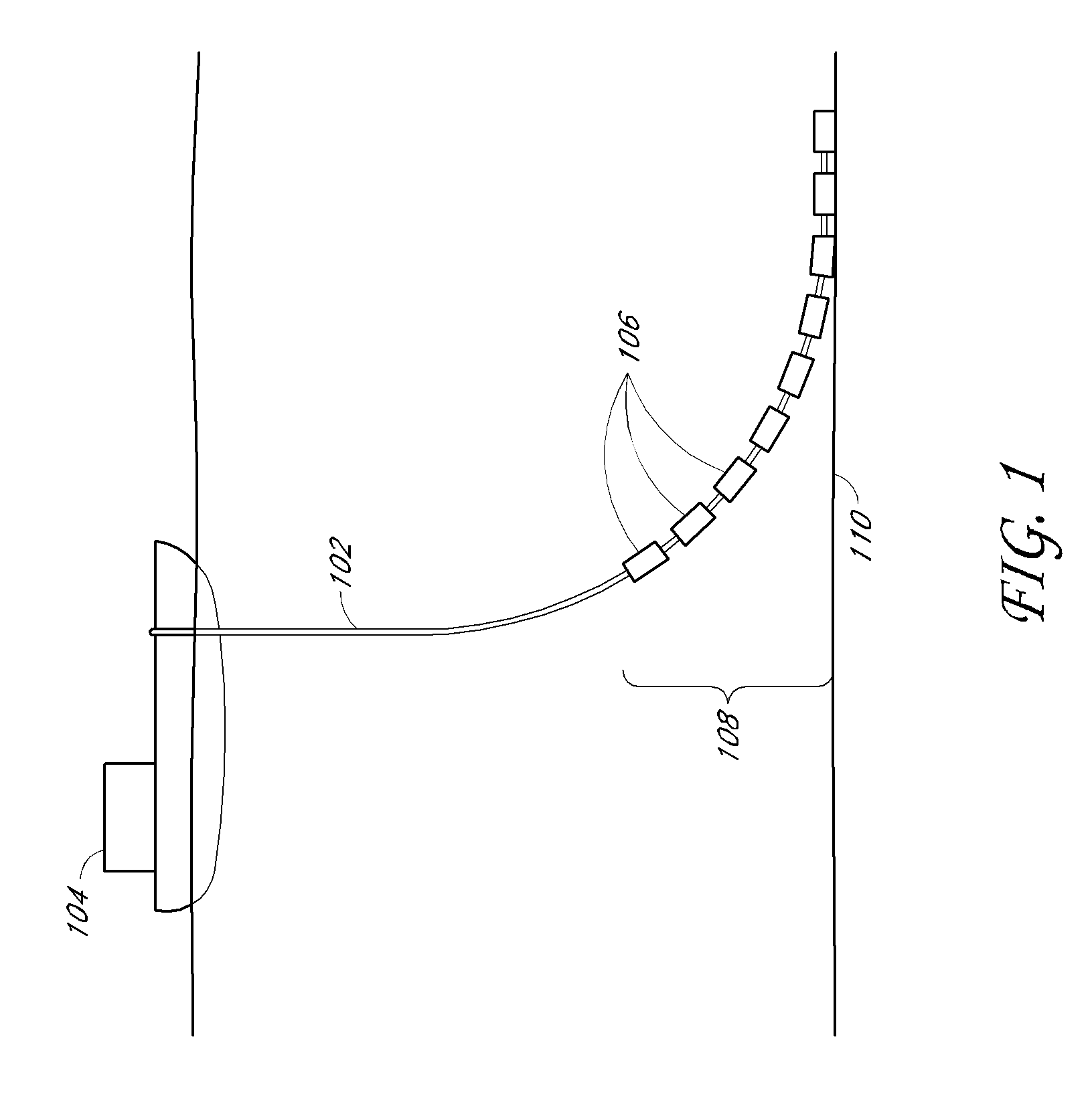
[0019]An overview of a typical layout of a pipe extending between a floating offshore platform and the well site of an operation for the production of oil or gas is illustrated in FIG. 1. As shown in the figure, in a typical configuration, insulated steal pipe 102 extends from an oil tanker 104 or other platform toward a well of a drilling operation. The pipe 102 extends downward from the boat 104 into contact with the seafloor with significant sag. The sag in the pipe 102 allows the boat 104 to move relative to the well without instantly breaking the pipe 102. Such a pipe can be used for production, i.e., collection of gas, oil, or other fluids from the well, or for other purposes.

[0020]The area of the pipe that nears and comes in contact with the sea floor 110 is often referred to as the touch down zone (or TDZ) 108. It is at this general location that the largest strains of the pipe usually occur, as the pipe 102 is bent as the platform or ship 104 moves in response to the swell,...


PUM

PropertyMeasurementUnit
water absorptionaaaaaaaaaa
timeaaaaaaaaaa
lengthaaaaaaaaaa

Abstract

This disclosure provides methods and apparatuses to monitor strain in a steel pipe with reduced or eliminated disruption of the insulative and anti-corrosive layers or coatings that cover the pipe. The methods and apparatuses can include an attachment scheme that is less intrusive and less sensitive to dilation of the insulation layer on the pipe than previous strain monitoring solutions. Additionally, methods and apparatuses can reduce corrosion by virtue of the reduction in the number and volume of metallic components.

Description

CROSS-REFERENCE TO RELATED APPLICATIONS[0001]This application relates to and claims the benefit of U.S. Provisional Application No. 60 / 943,275, titled “Device and Method for Providing Strain Testing” and filed Jun. 11, 2007, the entirety of which is incorporated herein by reference.BACKGROUND[0002]1. Field[0003]The present development relates to monitoring equipment, for example, monitoring the strain on a section of underwater pipe.[0004]2. Description of the Related Art[0005]Gas and oil drilling is performed in many different ways, on land and at sea. In marine drilling operations, large sections of steel pipe, often referred to as “catenary risers,” are connected to stretch deep into the ocean and along the seabed. The length of this piping required to reach the sea floor, the pressure extremes, and the temperature extremes to which such pipe is subjected often result in undesirable strain and / or bends in the pipe.[0006]The resulting bending strains the tolerances of the pipe. Un...

Claims


Application Information

Patent Timeline
Patent Type & Authority Applications(United States)
IPC IPC(8): H01L41/00G01L9/06
CPCG01L5/102G01B21/32E21B17/015
Inventor EDWARDS, JR., RODERICK Y.MAIL, ANDREW RUSSELLKINNEY, MATHEW J.
Owner BMT SCI MARINE SERVICES
Why Eureka
Try Eureka