Rotary Joint

a rotary joint and high frequency technology, applied in the direction of coupling device connection, waveguide type device, mechanical apparatus, etc., can solve the problems of most mechanical and electrical or high frequency problems within the component, bearing damage, and fluctuation of electrical transmission properties, so as to achieve the general constant diameter of the air bearing gap

Inactive Publication Date: 2008-12-11
SPINNER
View PDF8 Cites 9 Cited by
  • Summary
  • Abstract
  • Description
  • Claims
  • Application Information

AI Technical Summary

Benefits of technology

[0006]The present invention is directed toward a high frequency rotary joint including a stator that at least partially encloses a rotor. The rotor is mounted in the stator in a contact-free manner. That is, contact between the rotor and the stator is prevented through the use of at least one radial air bearing and at least one axial air bearing. Air bearings are formed when air is pressed into the gap between opposed, movable parts via numerous microscopic holes. The diameter of the air bearing gap is generally constant. The air bearings effectively create an air cushion, preventing contact between the rotor with the stator. The bearing air flowing through the air bearing then simultaneously acts as cooling air for the high-frequency coupled parts that heat up considerably depending on the transmitted output.

Problems solved by technology

These bearings, however, create the most mechanical and electrical or high frequency problems within the component.
Increased friction regularly causes bearing damage, and increased play causes the electrical transmission properties to fluctuate.
Additional disadvantages with these bearings are lubricant drainage at high temperatures, low resistance to corrosion of the roller bearings, and insufficient seal against the high frequency area, which is frequently kept at an elevated internal pressure by means of pre-dried air to improve the electric strength.
HF rotary joints including rolling bearings, therefore, must undergo frequent expensive and time-consuming servicing, including a readjustment of the electrical properties after each servicing.

Method used


Image

  • Rotary Joint
  • Rotary Joint
  • Rotary Joint

Examples


Embodiment Construction

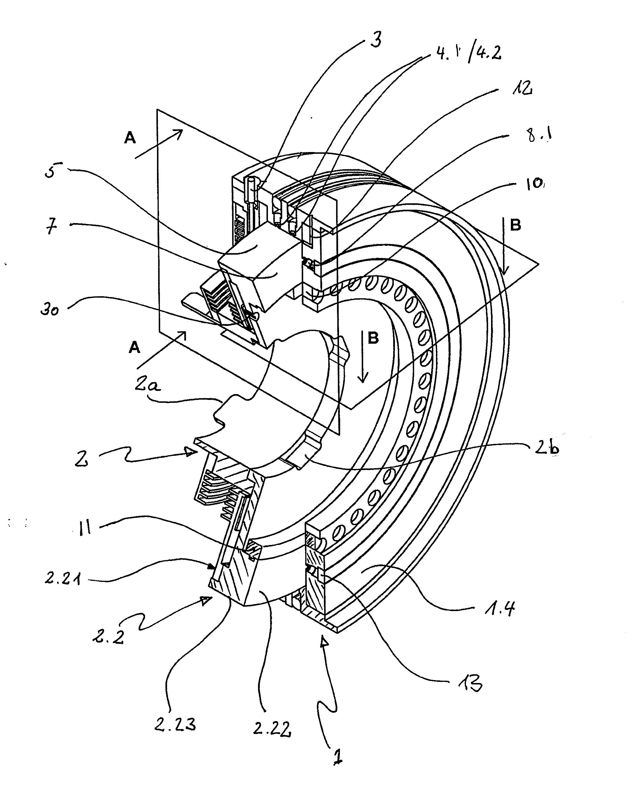
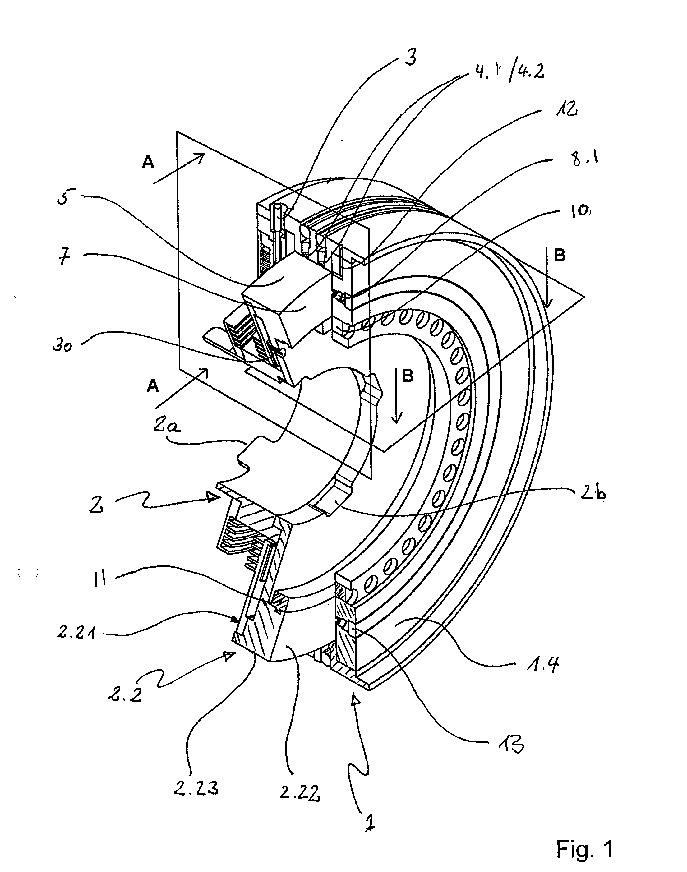
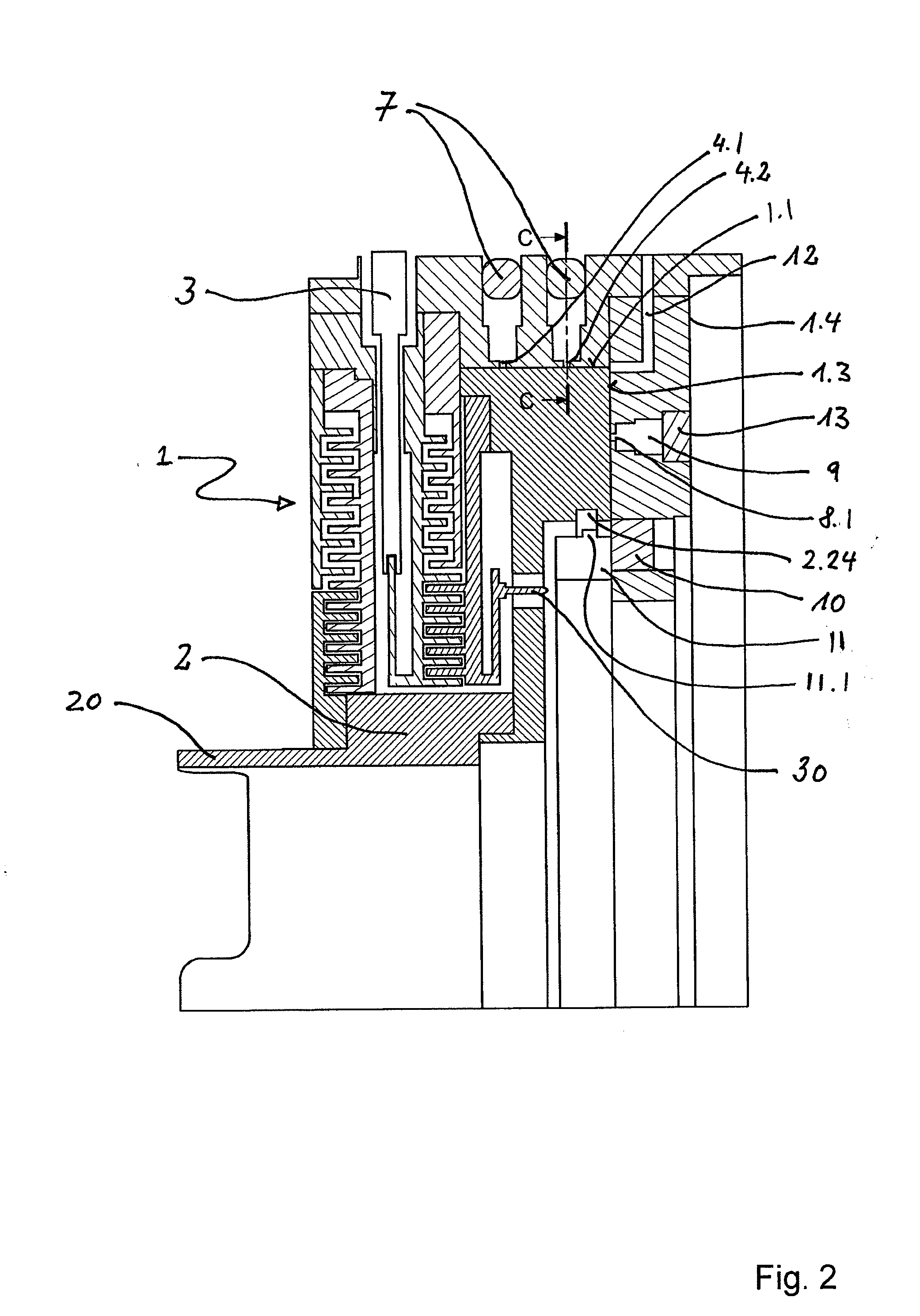
[0023]FIGS. 1-4 illustrate a rotary joint (coupling) in accordance with an embodiment of the invention, showing a configuration having a radial air bearing and an axial air bearing. Referring to FIG. 1, a stator 1 includes a rotor 2 mounted within the stator via a radial air bearing and an axial air bearing. In terms of high frequency engineering, the stator 1 forms the outer conductor for a coaxial connection to a first inner conductor 3. The stator 1 indirectly contacts the rotor 2 via a plurality of folded λ / 4 lines in a galvanically-contactless manner. The rotor 2 coaxially connects with a second inner conductor 30 at a point along its perimeter to receive or supply high frequency (HF) signals.

[0024]The rotor 2 includes driver tabs 2a and driver recesses 2b for connecting to, e.g., a rotary drive and / or a radar antenna. The rotor 2 may include a flange ring 2.2 that engages a hollow cylindrical section of the stator 1. The flange ring 2.2 possesses a first generally annular face...


PUM


Abstract

A high frequency (HF) rotary joint including a rotor and a stator is disclosed. The rotor is connected to the stator by a high frequency connection via a λ/4 line. The rotor, moreover, is mounted in the stator utilizing at least one radial aircushion bearing and at least one axial aircushion bearing. The bearings prevent contact between the rotor and the stator.

Description

CROSS REFERENCE TO RELATED APPLICATIONS[0001]This application claims priority under 35 U.S.C. §119 to Application No. DE 102007026431.5 filed on 06 Jun. 2008, entitled “HF Rotary Joint with a λ / 4 Line Between the Stator and Rotor,” the entire contents of which are hereby incorporated by reference.FIELD OF THE INVENTION[0002]The invention is directed toward a high frequency rotary coupling and, in particular, a rotary joint including a stator that at least partially encloses a rotor, wherein the rotor has a high frequency connection to the rotor.BACKGROUND OF THE INVENTION[0003]High frequency (HF) rotary joints (also called rotary couplings) typically have single channel or multichannel coaxial or hollow conductor couplings. In one configuration, an array transmits a wide-band electric signal between at least two components disposed for rotation relative to each other. The components are provided with coupling surfaces that are maintained at a largely constant distance from each othe...

Claims


Application Information

Patent Timeline
Patent Type & Authority Applications(United States)
IPC IPC(8): H01P1/06
CPCH01P1/062F16C32/0622F16C32/0696H01R13/646H01R39/64H01R35/02
Inventor FISCHER, FRANZSTADLER, CHRISTIAN
Owner SPINNER
Why Eureka
Try Eureka