Exposure apparatus

Inactive Publication Date: 2008-12-11
CANON KK
View PDF15 Cites 11 Cited by
  • Summary
  • Abstract
  • Description
  • Claims
  • Application Information

AI Technical Summary

Benefits of technology

[0008]The present invention is directed to an exposure apparatus that effici

Problems solved by technology

However, the mirror oxidizes or deposits carbon or carbide on its surface due to a residue gas in the vacuum chamber and the influence of degas from the resist applied to a substrate of a wafer.
These contaminations would degrade the mirror's optical performance.
JP 2006-49758 does not consi

Method used


Image

  • Exposure apparatus
  • Exposure apparatus
  • Exposure apparatus

Examples


first embodiment

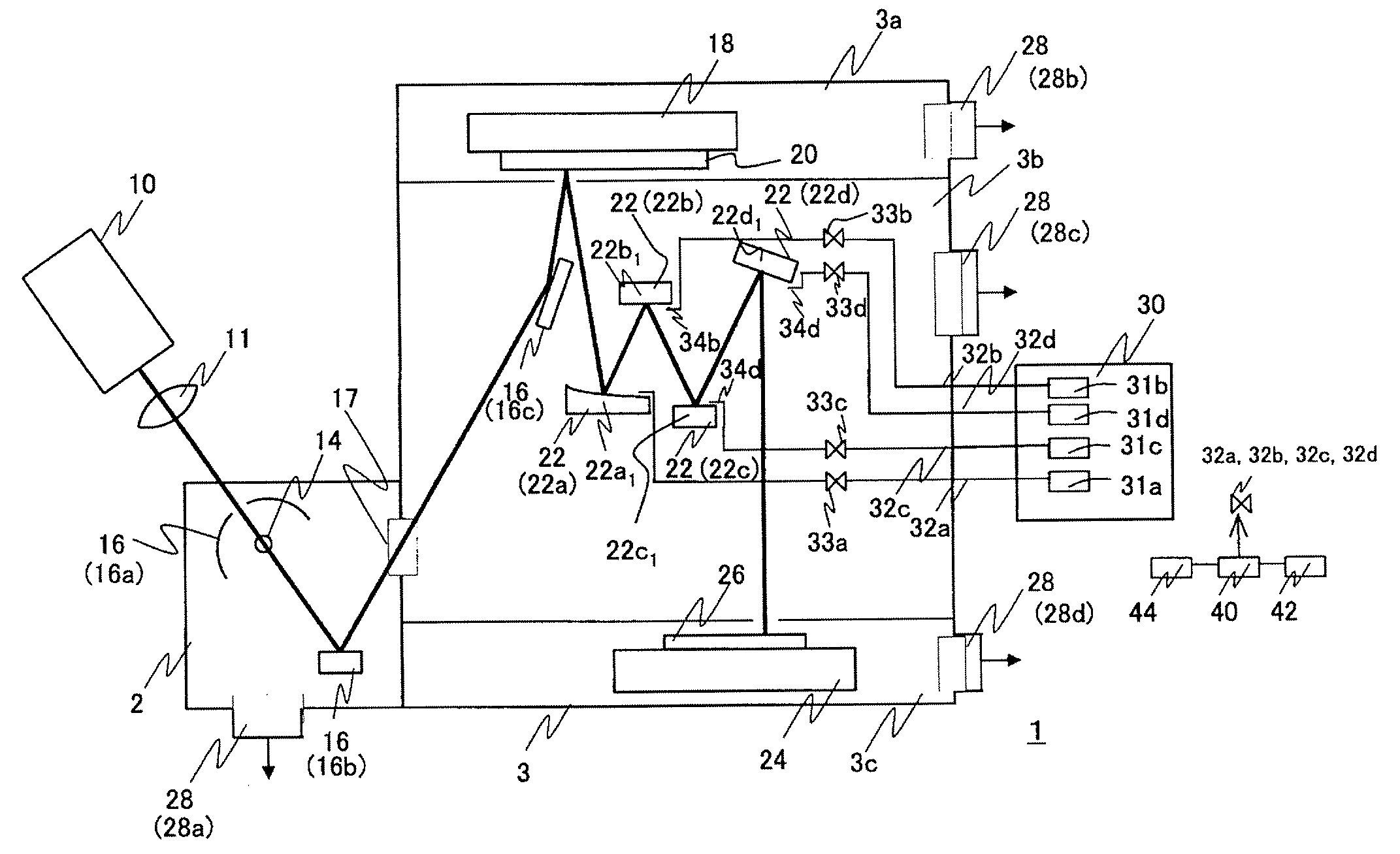
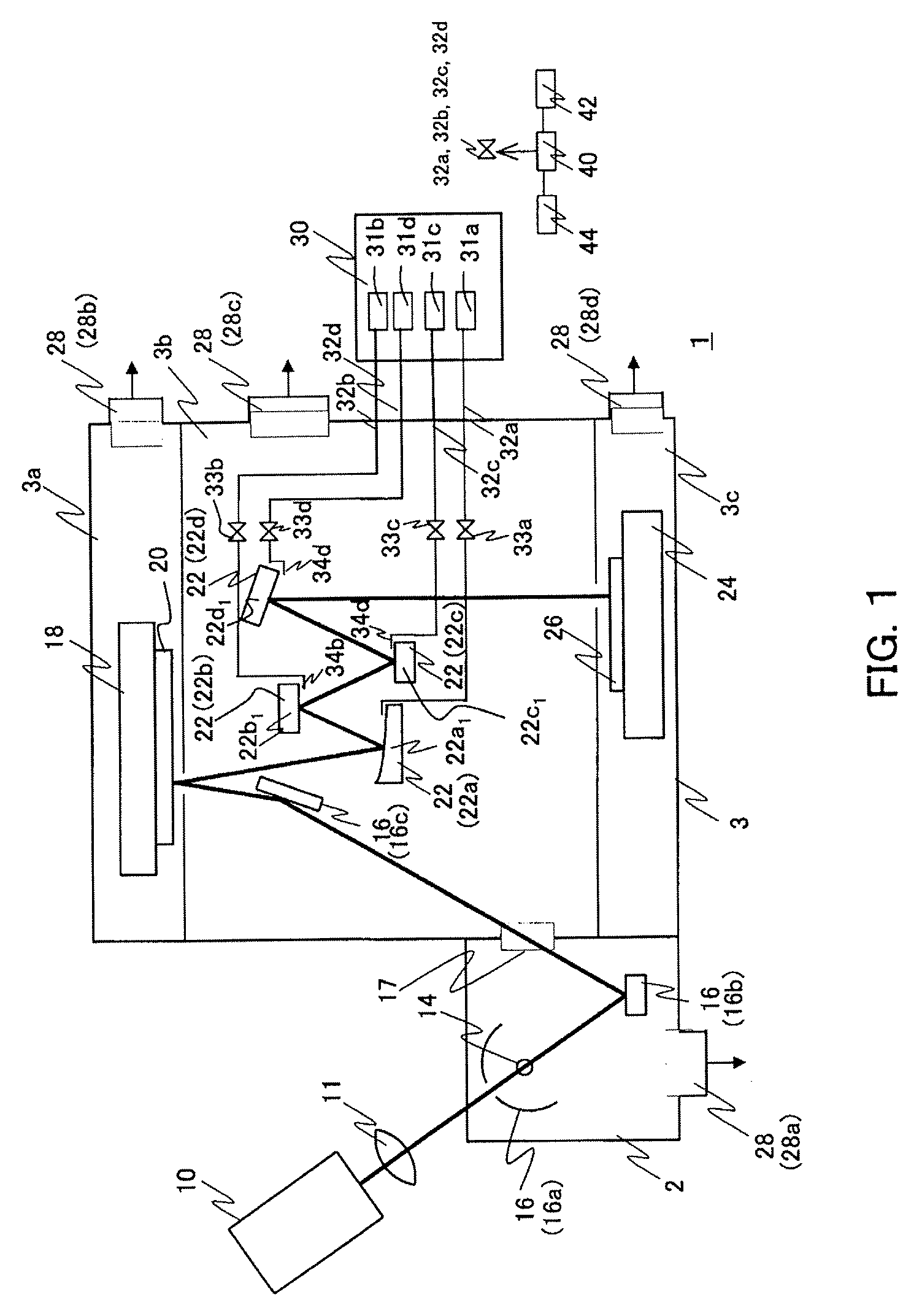
[0019]FIG. 1 is a schematic block diagram of a EUV exposure apparatus 1 according to one embodiment of the present invention. A laser beam emitted from a laser 10 is condensed by a lens 11. The EUV light radiated from a plasma spot 14 formed at a condensing point is condensed by an illumination optical system 16. The illumination optical system 16 includes an elliptical mirror 16a, an integrator 16b, and a deflection mirror 16c, and introduces the EUV light to a reflection reticle 20. A projection optical system 22 projects the light reflected from the reflection reticle 20 onto a wafer 26. The reticle 20 is fixed onto a translatable reticle stage 18, and the wafer 26 is fixed onto a translatable wafer stage 24. The EUV exposure apparatus 1 uses light for exposure which has a wavelength between 10 nm and 20 nm, and achieves a high resolution through the short wavelength. The EUV light source may use a synchrotron radiation light source, a discharge induced plasma light source, or th...

second embodiment

[0037]While the first embodiment houses the mirrors 22a to 22d in one vacuum chamber 3b, the second embodiment houses them in different vacuum chambers according to the types of supplied gases. FIG. 3 shows principle part of a EUV exposure apparatus 1A of this embodiment.

[0038]The vacuum chamber 3 has vacuum chambers 3a, 3b1, 3b2, and 3c. The vacuum chamber 3a houses the reticle stage 18, the reticle chuck 19, and the reticle 20. The vacuum chamber 3b1 houses the mirrors 22a to 22d in six-mirror projection optical system 22. The vacuum chamber 3b2 houses the mirrors 22e and 22f in the projection optical system 22. 23 denotes a mirror holder. The vacuum chamber 3c houses the wafer stage 24, the wafer chuck 25, and the wafer 26. The vacuum chambers 3a and 3c are substantially the same as those shown in FIG. 1. Moreover, while the exposure apparatus includes plural vacuum chambers, such as a vacuum chamber that houses an illumination optical system (not shown), a vacuum chamber that ho...

third embodiment

[0043]FIG. 4 is a schematic block diagram of the EUV exposure apparatus 1B according to a third embodiment. The EUV exposure apparatus 1B has a basic structure similar to that of the EUV exposure apparatus 1, but is different in that the EUV exposure apparatus 1B can control the illuminance, the wavelength and the illuminated region of the exposure light, and includes a mechanism configured to generate necessary electromagnetic waves. In addition, another light source different from the exposure light may be provided as necessary.

[0044]In the maintenance, the exposure apparatus 1B irradiates the electromagnetic waves onto the optical elements as necessary, and the illuminance, wavelength, and the illuminated region of the electromagnetic waves are adjusted suitable for each optical element. In addition, the illuminance, wavelength, and the illuminated region of the irradiated electromagnetic waves may be made variable according to the state of each optical element.

[0045]The exposure...


PUM


Abstract

An exposure apparatus exposes a substrate using light from a light source having a wavelength of 20 nm or smaller, and includes plural optical elements, each of which is configured to reflect the light, plural vacuum chambers, each of which houses one or more of the plural optical elements, and a gas supplier configured to supply to each vacuum chamber independently a gas used to inhibit contaminations that could occur on the optical element housed in each vacuum chamber, wherein the gas supplier supplies different types of gases to the plural vacuum chambers according to an illuminance of an illumined region on the optical element housed in each vacuum chamber.

Description

BACKGROUND OF THE INVENTION[0001]The present invention relates to an exposure apparatus that uses extreme ultraviolet (“EUV”) light, in particular, uses, as exposure light, light having a wavelength of 20 nm or smaller. This exposure apparatus will be referred to as a “EUV exposure apparatus” hereinafter.[0002]A projection exposure apparatus has conventionally been used to expose a pattern of a reticle (original) onto a wafer (substrate) via a projection optical system. The recent exposure apparatuses have been increasingly required to effectively expose finer patterns, and one proposed EUV exposure apparatus uses the EUV light having a wavelength smaller than that of the UV light to meet the high resolution demands.[0003]The light's absorption index into materials increases in the EUV light wavelength range, and the EUV exposure apparatus accommodates a catoptric optical system in a vacuum chamber. The catoptric optical system needs to maintain an optical performance (reflective ch...

Claims


Application Information

Patent Timeline
IPC IPC(8): G03B27/42
CPCG03F7/70808G03F7/70841G03F7/70916
Inventor KANEHIRA, MIKATERASHIMA, SHIGERUWATANABE, YUTAKA
Owner CANON KK
Why Eureka
Try Eureka