Method for measuring the concentration of a gas component in a measuring gas

Active Publication Date: 2008-12-11
SIEMENS AG
View PDF10 Cites 18 Cited by
  • Summary
  • Abstract
  • Description
  • Claims
  • Application Information

AI Technical Summary

Benefits of technology

[0011]The invention seeks to provide a simple method for meas

Problems solved by technology

The beam splitter and coupler invariably contribute to the noise of the system due to etalon effects.
The precision of this offse

Method used


Image

  • Method for measuring the concentration of a gas component in a measuring gas
  • Method for measuring the concentration of a gas component in a measuring gas
  • Method for measuring the concentration of a gas component in a measuring gas

Examples


Embodiment Construction

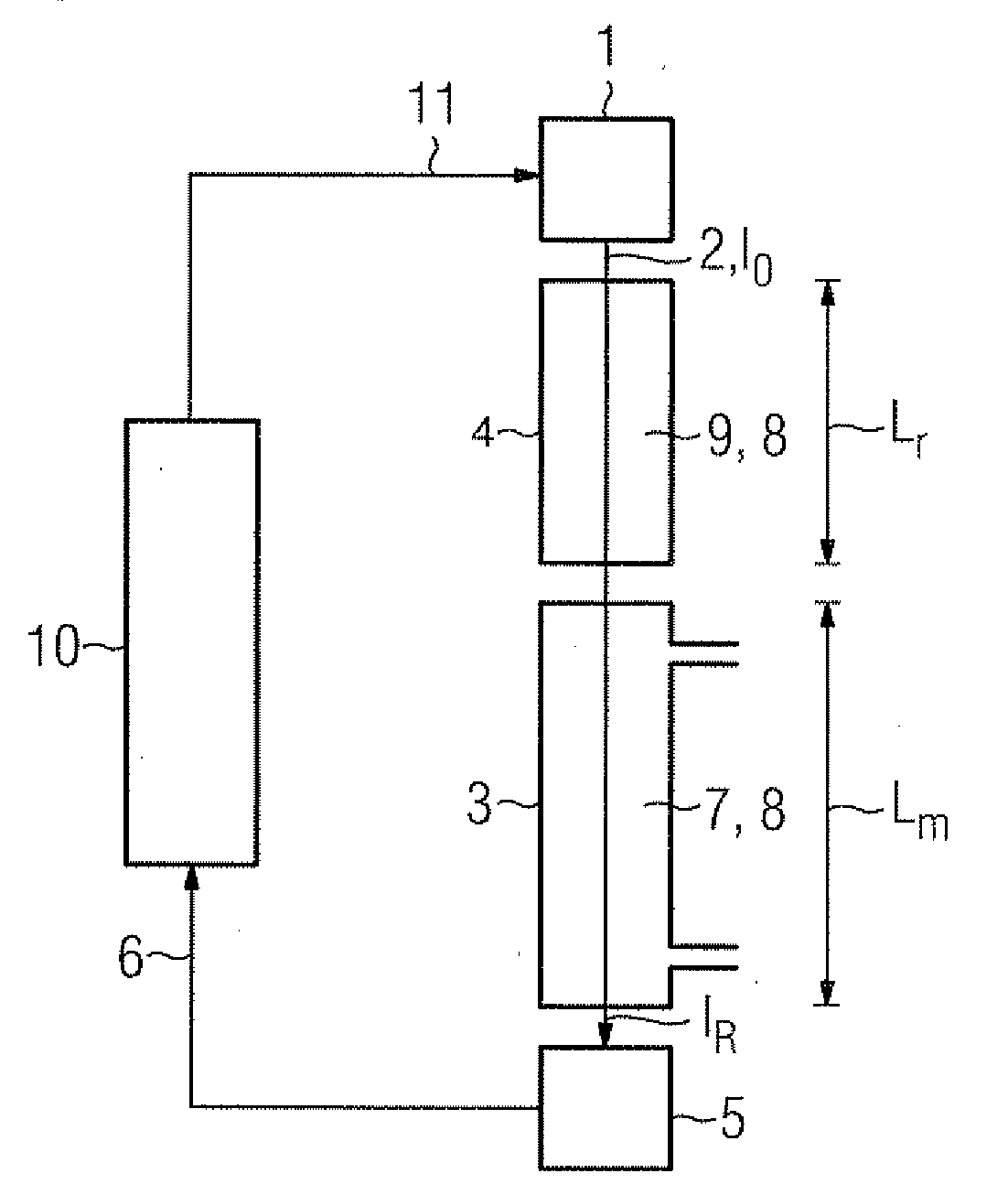
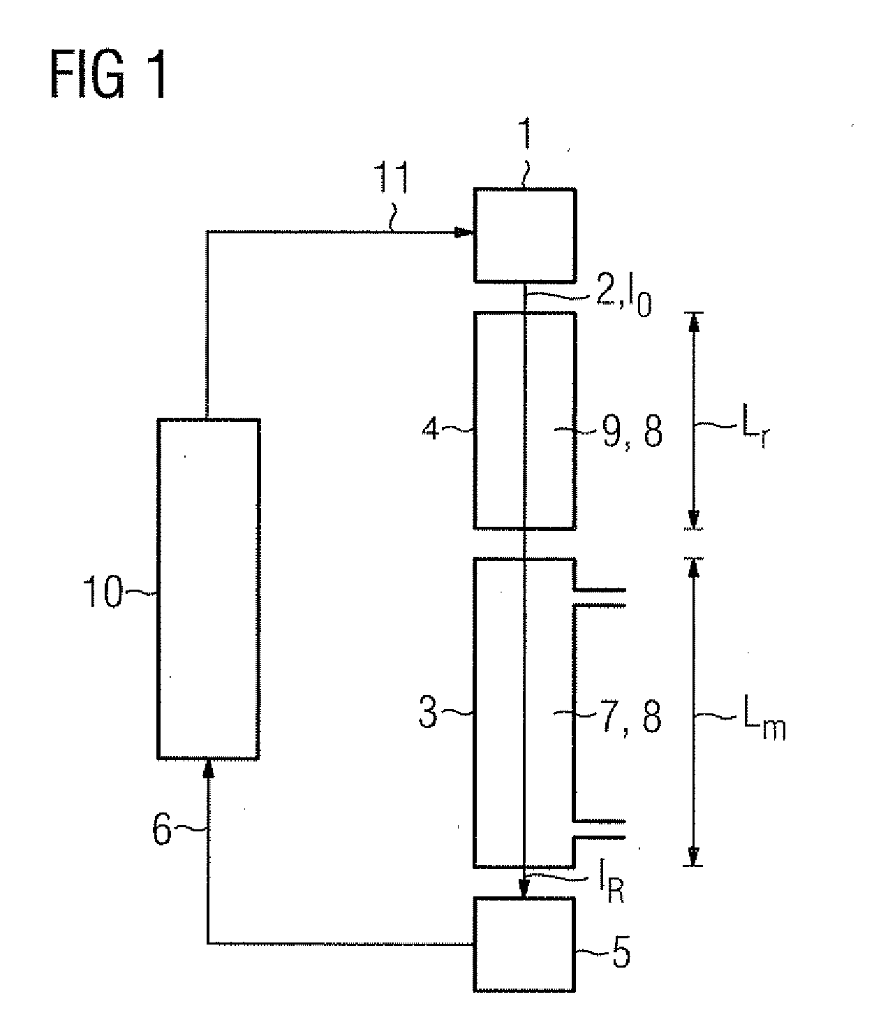
[0020]FIG. 1 shows a laser spectrometer as an example for an apparatus for practicing the present invention. The laser spectrometer includes a frequency (wavelength) tunable light source 1 in form of a diode laser for generating light 2 in form of a laser beam which is passed along a single optical path through a measuring volume 3 and a reference cell 4 to a detector 5 for generating a signal 6 indicative of the received light intensity. The measuring volume 3, which can be a sample cell or, in case of in-situ process measurements, a gas-leading pipe, furnace, funnel or the like, contains a measuring gas 7, in which the concentration of a specific gas component 8 is to be measured. The reference gas cell 4 contains a reference gas 9 which comprises the gas component 8 of interest in a known concentration. The signal 6 of the detector 5 is fed to an evaluation and controlling unit 10 for calculating the concentration of the gas component 8 in the measuring gas 7 and for controlling ...


PUM


Abstract

There is described a method for measuring a concentration of a gas component in a measuring gas, wherein the light of a wavelength tunable light source is passed along a single optical path through a measuring volume containing the measuring gas and a reference cell containing a reference gas to a detector. The reference cell is selected to contain a selected isotope of the gas component to be measured in a known abundance ratio higher than the known natural-abundance isotope ratio of the gas component in the measuring volume; the light source is tuned to sweep the wavelength of the light over the absorption lines of the selected isotope and the remaining gas component; and the concentration of the gas component in the measuring volume is calculated from the ratio of the detector signals at the peaks of the absorption lines, based on Lambert's law and taking into account the known abundance isotope ratios.

Description

CROSS REFERENCE TO RELATED APPLICATIONS[0001]This application claims priority of European Patent Office application No. 07011165.3 EP filed Jun. 6, 2007, which is incorporated by reference herein in its entirety.FIELD OF INVENTION[0002]The invention relates to a method for measuring the concentration of a gas component in a measuring gas, wherein the light of a wavelength tunable light source is passed along a single optical path through a measuring volume containing the measuring gas and a reference cell containing a reference gas to a detector for generating a signal indicative of the wavelength dependent absorption of the light, and wherein the reference gas comprises the gas component in a known concentration.BACKGROUND OF INVENTION[0003]Such a method is known from U.S. Pat. No. 6,353,225.[0004]In spectroscopic gas detection, the concentration of a known gas component in a gas mixture (measuring gas) is determined from a measured wavelength-specific absorption of the gas compone...

Claims


Application Information

Patent Timeline
IPC IPC(8): G01N21/00
CPCG01N21/39G01N2021/399
Inventor KLUCZYNSKI, PAWELLUNDQVIST, STEFAN
Owner SIEMENS AG
Why Eureka
Try Eureka