Protection for permanent magnet motor control circuits

a permanent magnet motor and control circuit technology, applied in emergency protective circuit arrangements for limiting excess voltage/current, emergency protective circuit arrangements, etc., can solve problems such as inverter malfunction, inconvenient operation, and inability to protect permanent magnet motors

Inactive Publication Date: 2008-12-11
GM GLOBAL TECH OPERATIONS LLC
View PDF9 Cites 90 Cited by
  • Summary
  • Abstract
  • Description
  • Claims
  • Application Information

AI Technical Summary

Benefits of technology

[0004]An inverter protection circuit is provided for protecting an inverter which operates from voltage supplied by a direct current (DC) bus to control a synchronous motor. The inverter protection circuit includes a protection controller and a power supply. The protection controller is coupled to the motor control circuit and detects predetermined motor control circuit fault conditions. The power supply is coupled to the DC bus and the protection controller for utilizing the voltage provided from the DC bus to power the protection controller.

Problems solved by technology

Malfunctions in such motor control circuits can be caused by a large number of potential problems.
For example, loss of bias power of the inverter, microprocessor malfunction, power switch malfunction or sensor malfunctions may cause the inverter to malfunction.
However, many such fault handling strategies provide multiple fault modes which require extraneous information to either employ one or more of the strategies or switch between utilization of the various strategies.

Method used


Image

  • Protection for permanent magnet motor control circuits
  • Protection for permanent magnet motor control circuits
  • Protection for permanent magnet motor control circuits

Examples


Embodiment Construction

[0010]The following detailed description is merely exemplary in nature and is not intended to limit the invention or the application and uses of the invention. Furthermore, there is no intention to be bound by any expressed or implied theory presented in the preceding technical field, background, brief summary or the following detailed description.

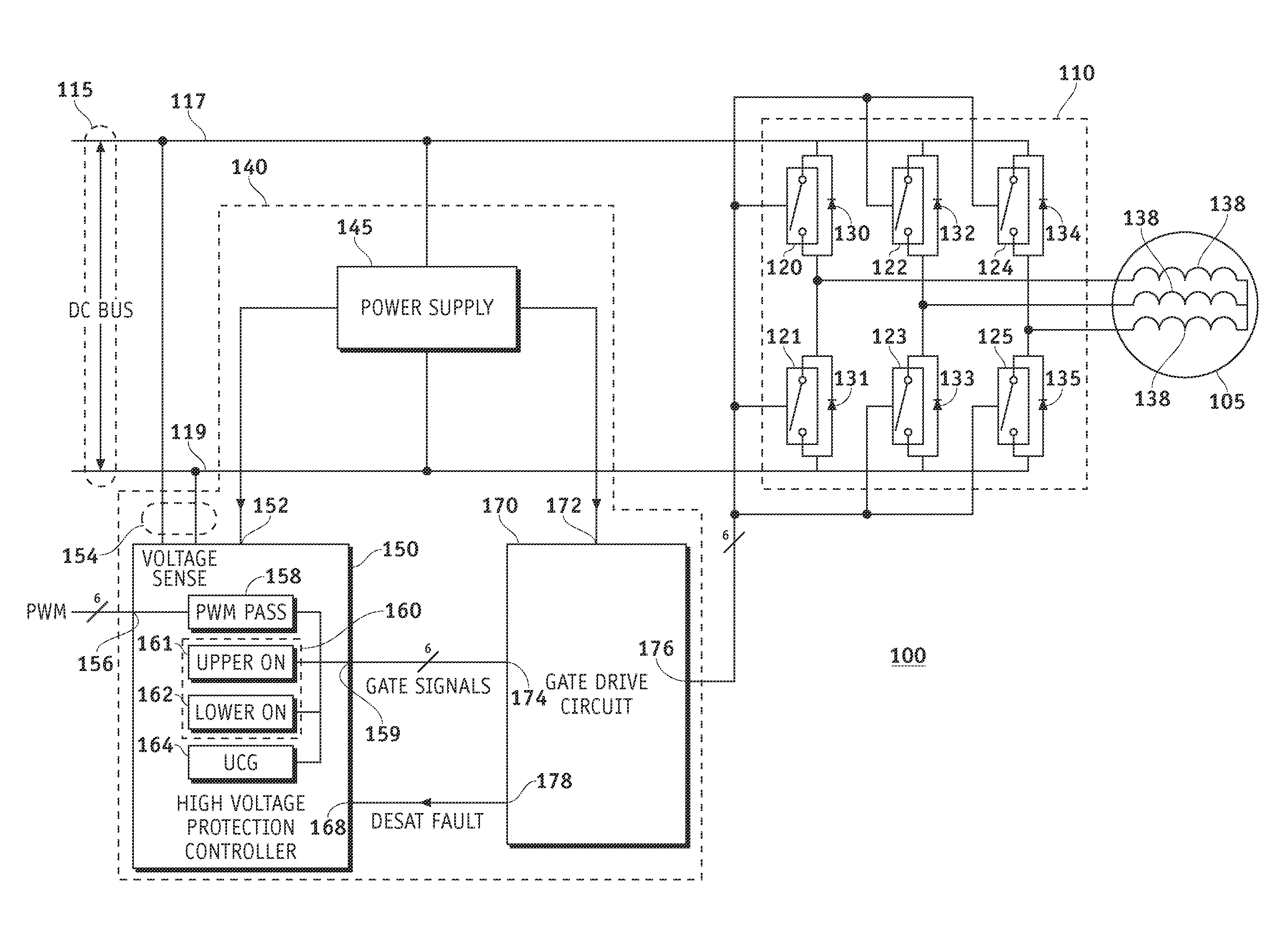
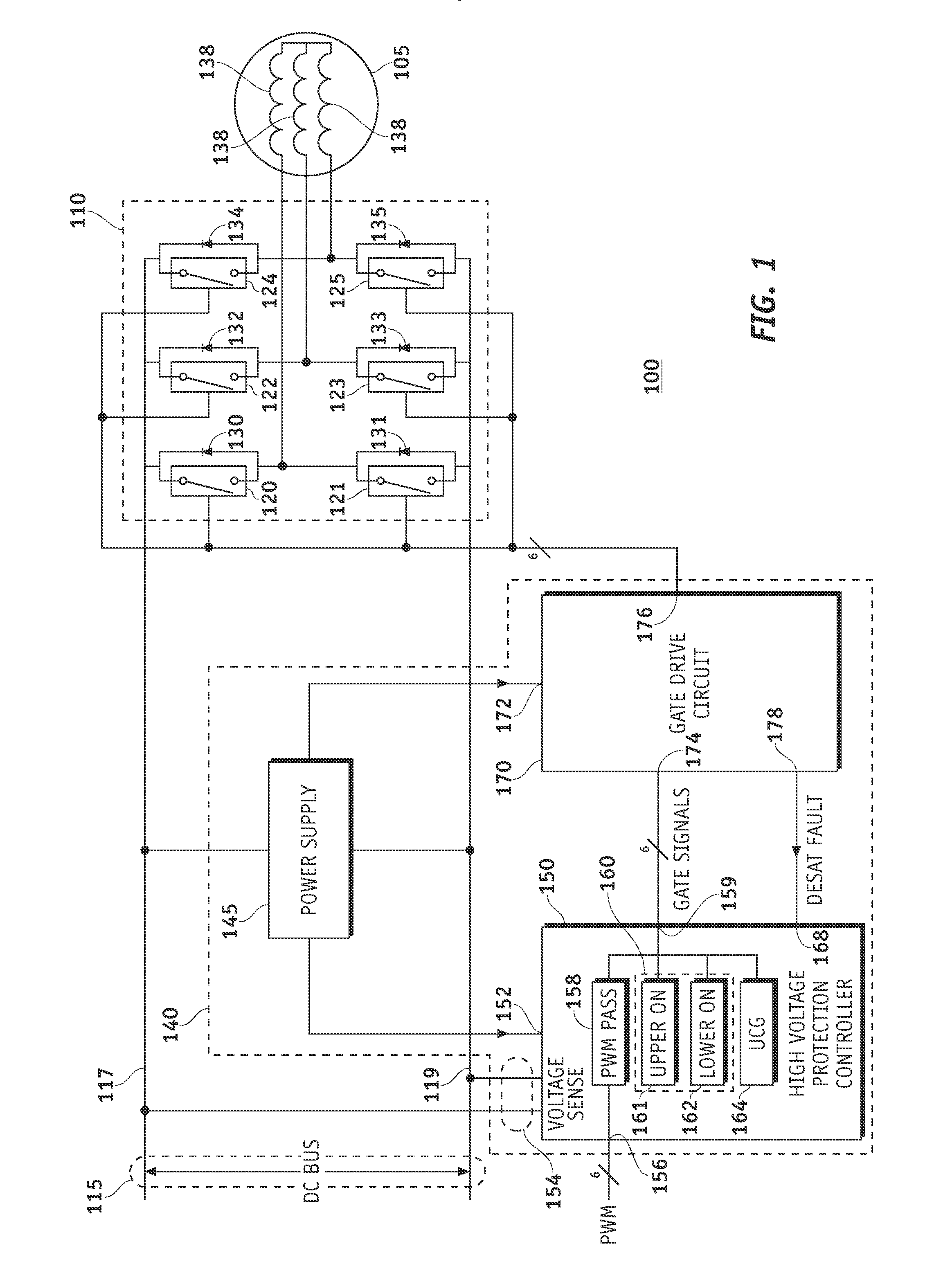
[0011]Referring to FIG. 1, a permanent magnet electric motor system 100, such as an electric drive system for a hybrid automobile, includes a permanent magnet electric motor 105, such as an interior permanent magnet (IPM) synchronous motor having three phases. A motor control circuit, such as an inverter 110, receives power from a power source (not shown), such as a battery or fuel cell, via a DC bus 115 having a high voltage node 117 and a low voltage node 119 and is coupled to the motor 105 for control thereof. The inverter 110 is, for example, a three phase voltage source inverter, such as the three-leg inverter 110 depicted in FIG. 1, ...


PUM


Abstract

Methods and apparatus are provided for protecting a motor control circuit in a permanent magnet electric motor system. The permanent magnet electric motor system includes a permanent magnet electric motor having a predetermined number of windings corresponding to the phases of the permanent magnet electric motor and a direct current (DC) bus coupled to a power source for providing operational power for the electric motor system. A motor control circuit is connected to the DC bus for receiving the operational power therefrom and is connected to the windings of the permanent magnet electric motor for controlling the permanent magnet electric motor. A protection circuit is connected to the DC bus for receiving the voltage therefrom for operation of the protection circuit and for detecting predetermined motor control circuit fault conditions from voltage sensed on the DC bus and in response thereto providing protection for the motor control circuit.

Description

TECHNICAL FIELD[0001]The present invention generally relates to permanent magnet electric motor systems, and more particularly relates to protection of permanent magnet motor control circuits, such as inverters, in permanent magnet electric motor systems.BACKGROUND OF THE INVENTION[0002]Permanent magnet electric motor systems typically include permanent magnet motor control circuits, such as inverters. Malfunctions in such motor control circuits can be caused by a large number of potential problems. For example, loss of bias power of the inverter, microprocessor malfunction, power switch malfunction or sensor malfunctions may cause the inverter to malfunction. In order to protect against such malfunctions, a fault handling strategy needs to be provided. However, many such fault handling strategies provide multiple fault modes which require extraneous information to either employ one or more of the strategies or switch between utilization of the various strategies.[0003]Accordingly, ...

Claims


Application Information

Patent Timeline
Patent Type & Authority Applications(United States)
IPC IPC(8): H02H7/09
CPCH02H7/0838H02H3/20H02H7/1222
Inventor TANG, DAVIDWELCHKO, BRIAN A.HITI, SILVASELOGIE, MARK L.
Owner GM GLOBAL TECH OPERATIONS LLC
Why Eureka
Try Eureka