Quantum cascade laser suitable for portable applications

Active Publication Date: 2008-12-11
DAYLIGHT SOLUTIONS
View PDF38 Cites 45 Cited by
  • Summary
  • Abstract
  • Description
  • Claims
  • Application Information

AI Technical Summary

Benefits of technology

[0005]The present applicants have recognized that a narrow operating range exists in which an intermittently operated quantum cascade laser can provide sufficient brightness for a laser sight or other similar application without active cooling. Further, power sensing feedback regula

Problems solved by technology

Unfortunately, conventional solid-state laser diodes h

Method used


Image

  • Quantum cascade laser suitable for portable applications
  • Quantum cascade laser suitable for portable applications
  • Quantum cascade laser suitable for portable applications

Examples


Embodiment Construction

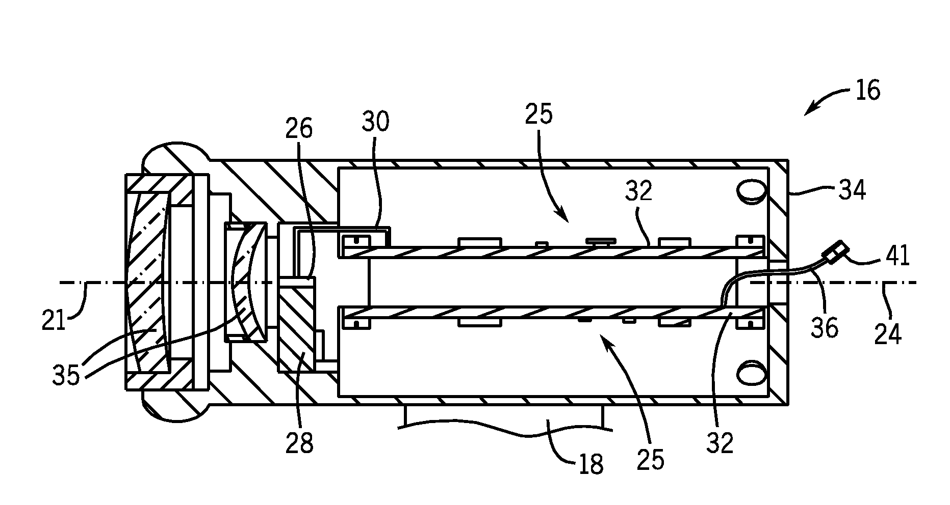
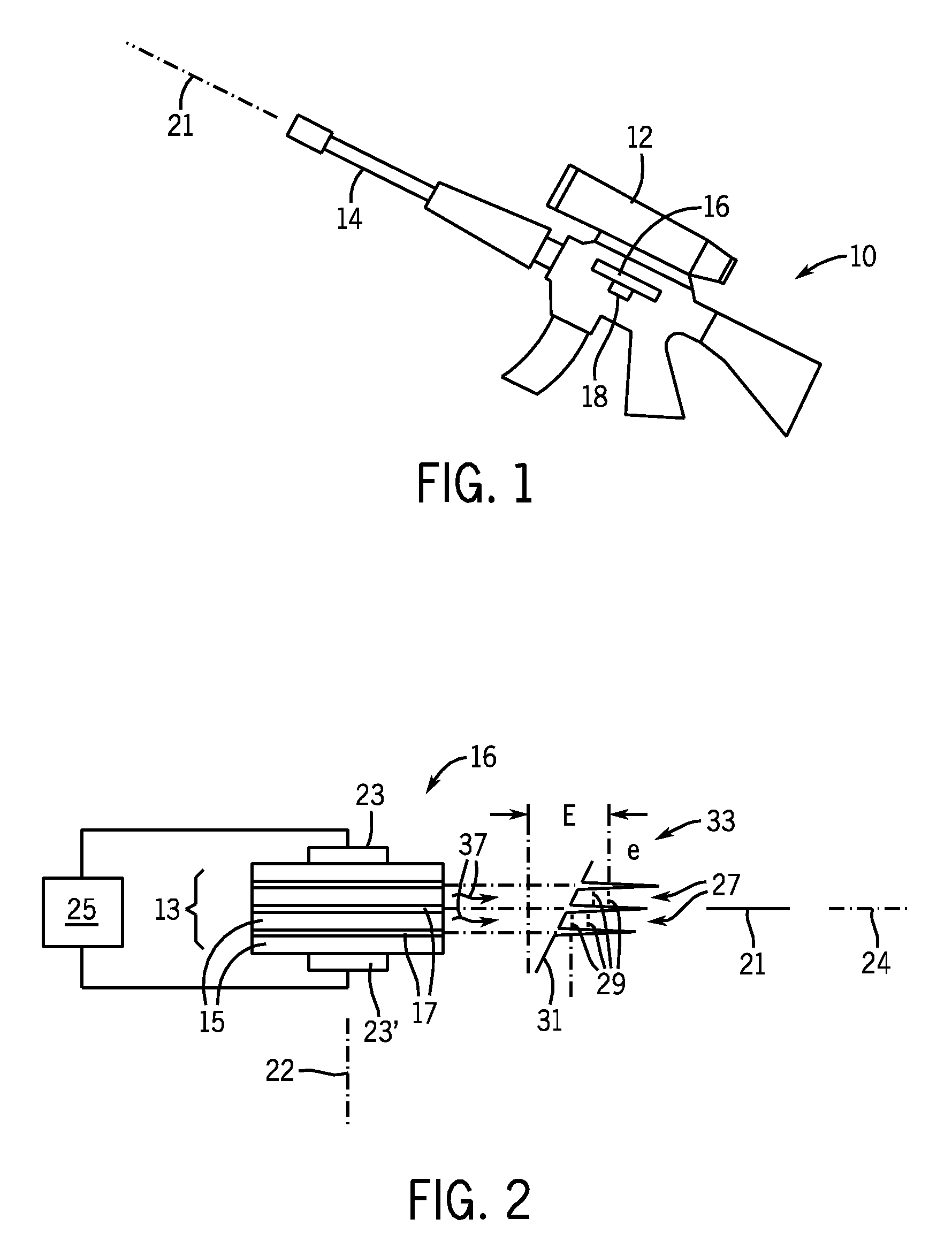
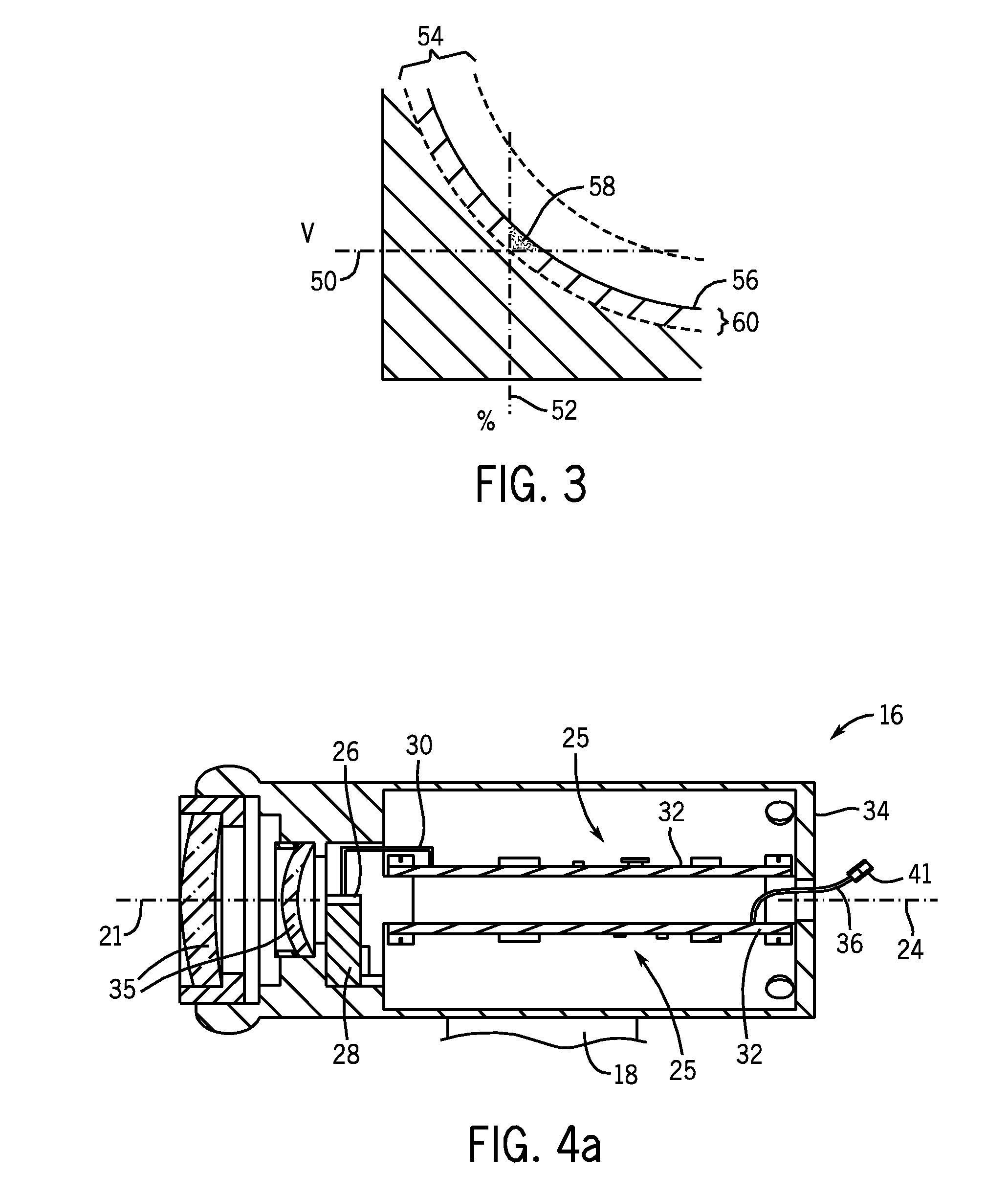
[0031]A possible substitute for a conventional laser diode in this application is the so-called quantum cascade laser. Unlike a conventional laser diode which relies on relatively large band gaps in solid-state semiconductors, the quantum cascade laser allows the development of sub bands with lower energy differences suitable for producing long wavelengths of infrared light. Because quantum cascade lasers do not rely on electron / hole annihilation to produce photons, multiple photons may be created for each electron providing high light power output. Such quantum cascade lasers require relatively high operating voltages and dissipate substantial heat. This heat ultimately inhibits the lasing action (reducing the number of photons per electron) and in the extreme can damage the device. For this reason it is known to use active cooling of the quantum cascade laser, for example with an electrically powered Peltier device and fan combination.

[0032]The large power consumption and high vol...


PUM


Abstract

A highly portable, high-powered infrared laser source is produced by intermittent operation of a quantum cascade laser power regulated to a predetermined operating range that permits passive cooling. The regulation process may boost battery voltage allowing the use of more compact, low-voltage batteries.

Description

CROSS-REFERENCE TO RELATED PATENT APPLICATIONS[0001]This application claims priority under 35 U.S.C. § 119(e) of U.S. Provisional Application Ser. No. 60 / 934952, filed Mar. 12, 2007, and of U.S. Provisional Application Ser. No. 61 / 035,283, filed Mar. 10, 2008, each of which is hereby incorporated by reference in its entirety for all purposes.BACKGROUND OF THE INVENTION[0002]The present invention relates to laser systems and, in particular, to compact lasers suitable for military, handheld weapon targeting systems, for example.[0003]Laser targeting systems, often called laser sights, may use a lightweight laser mounted to a gun so that its beam is generally aligned with the bore of the gun. In this position, the laser may project a small illuminated spot on the target assisting in alignment of the weapon. In order for the spot to be seen in bright environments and to project for an adequate distance, a continuous wave solid-state laser of high power is normally employed.[0004]In a mi...

Claims


Application Information

Patent Timeline
IPC IPC(8): H01S3/13H01S5/00H01S3/04
CPCB82Y20/00H01S5/005H01S5/02208H01S5/02288H01S5/024H01S5/042H01S5/02469H01S5/06216H01S5/06808H01S5/0683H01S5/3402G01J3/28F41G1/36H01S5/0428H01S5/02253
Inventor MARSLAND, JR., ROBDAY, TIMOTHY
Owner DAYLIGHT SOLUTIONS
Why Eureka
Try Eureka