
Shared memory for multi-core processors

Inactive Publication Date: 2008-12-11
BOSTON CIRCUITS
View PDF9 Cites 34 Cited by
  • Summary
  • Abstract
  • Description
  • Claims
  • Application Information

AI Technical Summary

Benefits of technology

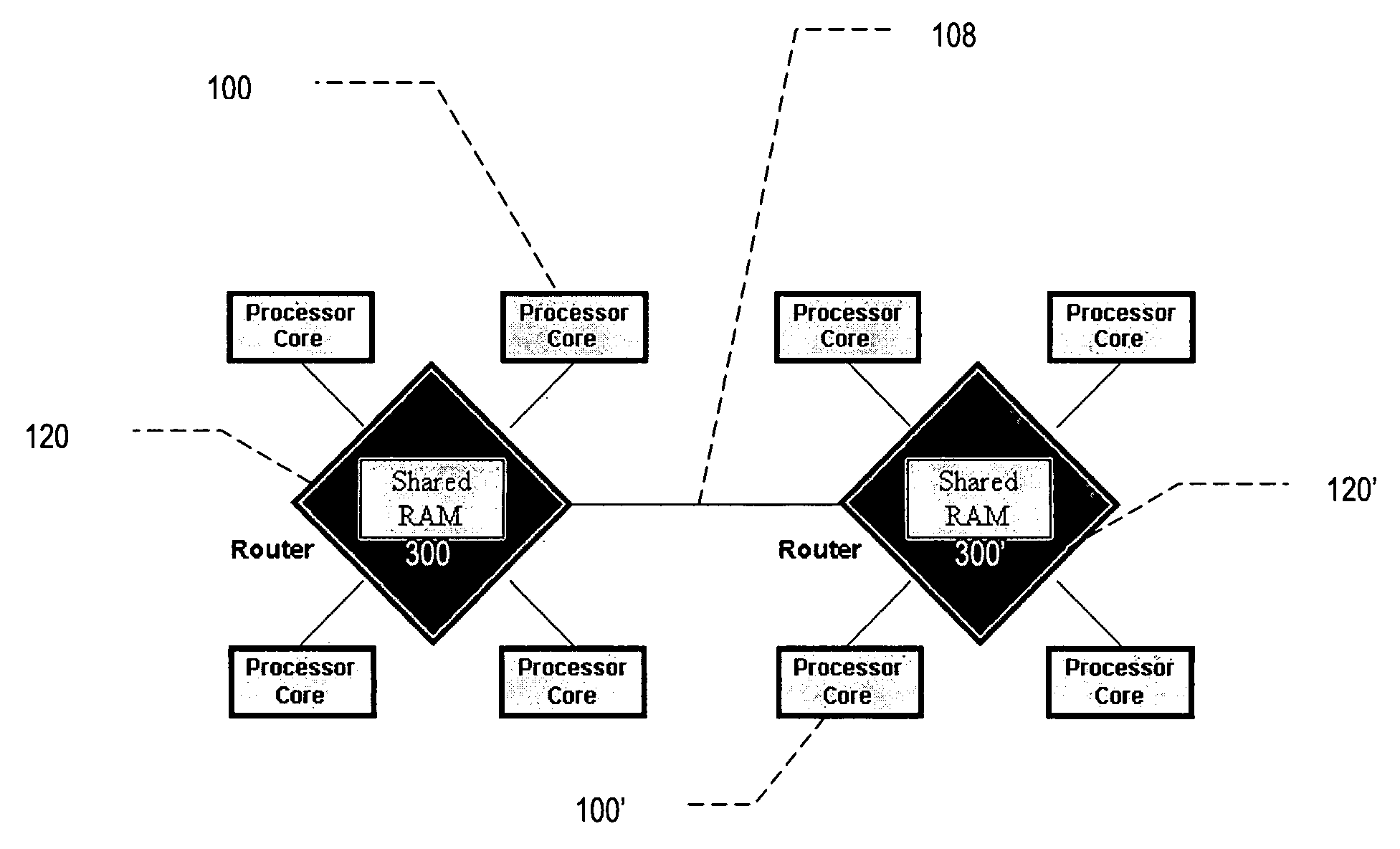
[0007]The present invention addresses the need for on-chip memory in multi-core processors by integrating memory with the network components, e.g., the routers and switches, that make up the processor's on-chip interconnect. Integrating memory directly with interconnect components provides several advantages: (a) low latency access for cores that are directly connected to the router / switch, (b) reduced interconnect traffic by keeping accesses with directly connected nodes local, (c) easily shared memory across multiple cores which may or may not be directly connected to the router / switch, (d) a memory that can be used as a Level 1 cache if the cores themselves have no cache, or as Level 2 cache if the cores already have a Level 1 cache, and (e) a memory that can be configured for use as a cache memory, shared memory, or context store. The memory may be configured to support a memory coherency protocol which can transmit coherency information on the interconnect. In this case too, it is advantageous from a traffic efficiency perspective to have the memory integrated into the fabric of the interconnect, i.e., with the routers / switches.
[0008]By reducing latency for memory access by the cores, embodiments of the present invention improve overall system performance. By providing an easily shareable on-chip memory with efficient access, embodiments of the present invention provide for improved inter-core communications in a multi-core microprocessor. Furthermore, embodiments of the present invention can reduce data traffic on the interconnect, thereby reducing overall power consumption.

Problems solved by technology

The computing resources required for applications such as multimedia, networking, and high-performance computing are increasing in both complexity and in the volume of data to be processed.
At the same time, it is increasingly difficult to improve microprocessor performance simply by increasing clock speeds, as advances in process technology have currently reached the point of diminishing returns in terms of the performance increase relative to the increases in power consumption and required heat dissipation.
Furthermore, multi-core processors typically employ a more complex interconnect mechanism to connect the cores, caches, and external memory interfaces that often includes switches and routers.

Method used


Image

  • Shared memory for multi-core processors
  • Shared memory for multi-core processors
  • Shared memory for multi-core processors

Examples


Embodiment Construction

Architecture

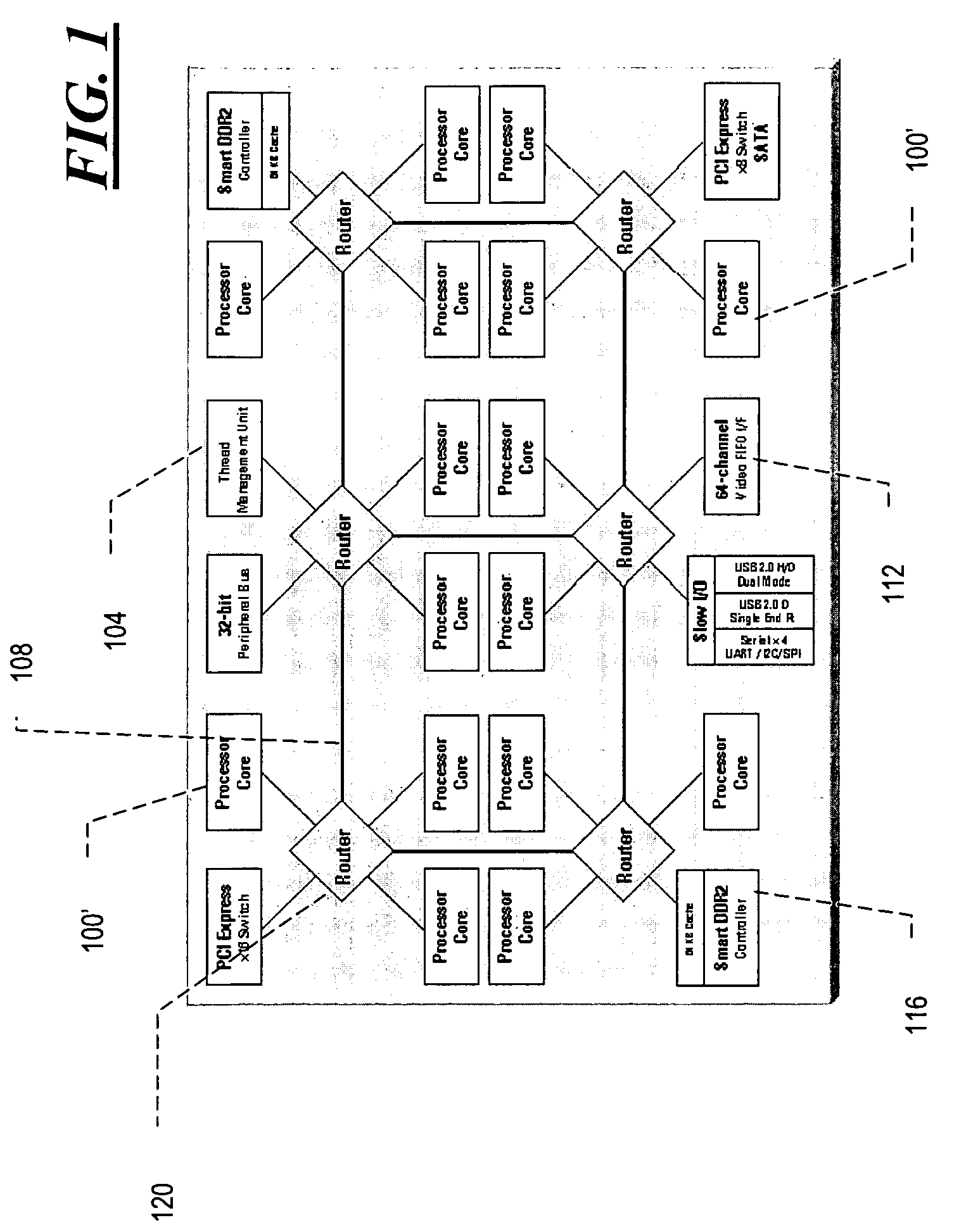
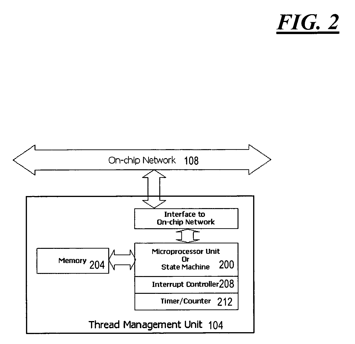
[0021]With reference to FIG. 1, a typical embodiment of the present invention includes at least two processing units 100, a thread-management unit 104, an on-chip network interconnect 108, and several optional components including, for example, function blocks 112, such as external interfaces, having network interface units (not explicitly shown), and external memory interfaces 116 having network interface units (again, not explicitly shown). Each processing unit 100 has a microprocessor core and a network interface unit. The processor core may have a Level 1 cache for data or instructions.

[0022]The network interconnect 108 typically includes at least one router or switch 120 and signal lines connecting the router or switch 120 to the network interface units of the processing units 100 or other functional blocks 112 on the network. Using the on-chip network fabric 108, any node, such as a processor 100 or functional block 112, can communicate with any other node. In a ty...


PUM


Abstract

A shared memory for multi-core processors. Network components configured for operation in a multi-core processor include an integrated memory that is suitable for, e.g., use as a shared on-chip memory. The network component also includes control logic that allows access to the memory from more than one processor core. Typical network components provided in various embodiments of the present invention include routers and switches.

Description

CROSS-REFERENCE TO RELATED APPLICATIONS[0001]The present application claims the benefit of co-pending U.S. provisional application No. 60 / 942,896, filed on Jun. 8, 2007, the entire disclosure of which is incorporated by reference as if set forth in its entirety herein.FIELD OF THE INVENTION[0002]The present invention relates to microprocessor memories, and in particular to memory shared among a plurality of processor cores.BACKGROUND OF THE INVENTION[0003]The computing resources required for applications such as multimedia, networking, and high-performance computing are increasing in both complexity and in the volume of data to be processed. At the same time, it is increasingly difficult to improve microprocessor performance simply by increasing clock speeds, as advances in process technology have currently reached the point of diminishing returns in terms of the performance increase relative to the increases in power consumption and required heat dissipation.[0004]To address the ne...

Claims


Application Information

Patent Timeline
IPC IPC(8): G06F15/76G06F9/02G06F9/46
CPCY02B60/1225G06F15/7842Y02D10/00
Inventor KURLAND, AARON S.KATAOKA, HIROYUKI
Owner BOSTON CIRCUITS
Learn More