Eureka AIR delivers breakthrough ideas for toughest innovation challenges, trusted by R&D personnel around the world.

Apparatuses, methods, and systems for time-multiplexing in a configurable spatial accelerator

a configurable spatial accelerator and time-multiplexing technology, applied in the field of electromechanical devices, can solve the problems of high energy cost, out-of-order scheduling, simultaneous multi-threading,

Inactive Publication Date: 2020-12-31
INTEL CORP
View PDF2 Cites 2 Cited by
  • Summary
  • Abstract
  • Description
  • Claims
  • Application Information

AI Technical Summary

Benefits of technology

The patent describes a new type of computer chip architecture called the CSA, which can achieve extremely high performance and energy efficiency compared to conventional computer designs. The CSA is a heterogeneous spatial array that targets direct execution of dataflow graphs, and it can be easily adapted to different computing uses. It includes a core that supports a wide range of instruction sets and a connected interconnect network that allows for low-latency accesses to memory. The chip also has a local cache that can be accessed quickly in parallel with other processor cores, ensuring coherency for shared data. Overall, the CSA provides a unique solution for high-performance computing and datacenter applications.

Problems solved by technology

Exascale computing goals may require enormous system-level floating point performance (e.g., 1 ExaFLOPs) within an aggressive power budget (e.g., 20 MW).
However, simultaneously improving the performance and energy efficiency of program execution with classical von Neumann architectures has become difficult: out-of-order scheduling, simultaneous multi-threading, complex register files, and other structures provide performance, but at high energy cost.
However, if there are less used code paths in the loop body unrolled (for example, an exceptional code path like floating point de-normalized mode) then (e.g., fabric area of) the spatial array of processing elements may be wasted and throughput consequently lost.
However, e.g., when multiplexing or demultiplexing in a spatial array involves choosing among many and distant targets (e.g., sharers), a direct implementation using dataflow operators (e.g., using the processing elements) may be inefficient in terms of latency, throughput, implementation area, and / or energy.
However, enabling real software, especially programs written in legacy sequential languages, requires significant attention to interfacing with memory.
However, embodiments of the CSA have no notion of instruction or instruction-based program ordering as defined by a program counter.
Exceptions in a CSA may generally be caused by the same events that cause exceptions in processors, such as illegal operator arguments or reliability, availability, and serviceability (RAS) events.
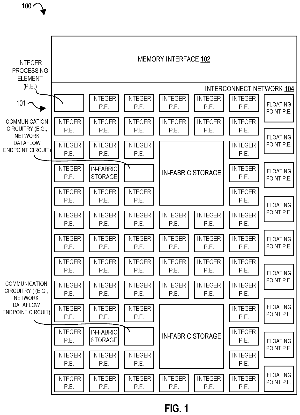
For example, in spatial accelerators composed of small processing elements (PEs), communications latency and bandwidth may be critical to overall program performance.
However, there may be support operations (e.g., outer loops) which do not execute every cycle and which could share same CSA resources without harming overall program performance.
However, more distant communication can take multiple cycles to occur.
In certain embodiments, a main energy cost of time-multiplexing is data toggling due to switching the network multiplexors.
However, this may limits the LICs that can be multiplexed to those that have a throughput of less than 0.5 tokens per cycle, and also remains wasteful of bandwidth in the case that the multiplexed LIC has a duty cycle below 0.5 tokens per cycle.
In certain embodiments, an issue in providing virtual channels is that the amount of buffering per channel is reduced.
Thus, if the buffer is reduced to one, synchronized time multiplexing may result in throughput loss due to the need to land new data from an upstream PE without having consumed previous data from a downstream PE.
In certain embodiments, an issue in providing virtual channels is that the amount of buffering per channel is reduced.
Thus, if the buffer is reduced to one, synchronized time multiplexing will result in throughput loss due to the need to land new data from an upstream PE without having consumed previous data from a downstream PE.

Method used


Image

  • Apparatuses, methods, and systems for time-multiplexing in a configurable spatial accelerator
  • Apparatuses, methods, and systems for time-multiplexing in a configurable spatial accelerator
  • Apparatuses, methods, and systems for time-multiplexing in a configurable spatial accelerator

Examples


Embodiment Construction

[0135]In the following description, numerous specific details are set forth. However, it is understood that embodiments of the disclosure may be practiced without these specific details. In other instances, well-known circuits, structures and techniques have not been shown in detail in order not to obscure the understanding of this description.

[0136]References in the specification to “one embodiment,”“an embodiment,”“an example embodiment,” etc., indicate that the embodiment described may include a particular feature, structure, or characteristic, but every embodiment may not necessarily include the particular feature, structure, or characteristic. Moreover, such phrases are not necessarily referring to the same embodiment. Further, when a particular feature, structure, or characteristic is described in connection with an embodiment, it is submitted that it is within the knowledge of one skilled in the art to affect such feature, structure, or characteristic in connection with other...


PUM


Abstract

Systems, methods, and apparatuses relating to time-multiplexing circuitry in a configurable spatial accelerator are described. In one embodiment, a configurable spatial accelerator (CSA) includes a plurality of processing elements; and a time-multiplexed, circuit switched interconnect network between the plurality of processing elements. In another embodiment, a configurable spatial accelerator (CSA) includes a plurality of time-multiplexed processing elements; and a time-multiplexed, circuit switched interconnect network between the plurality of time-multiplexed processing elements.

Description

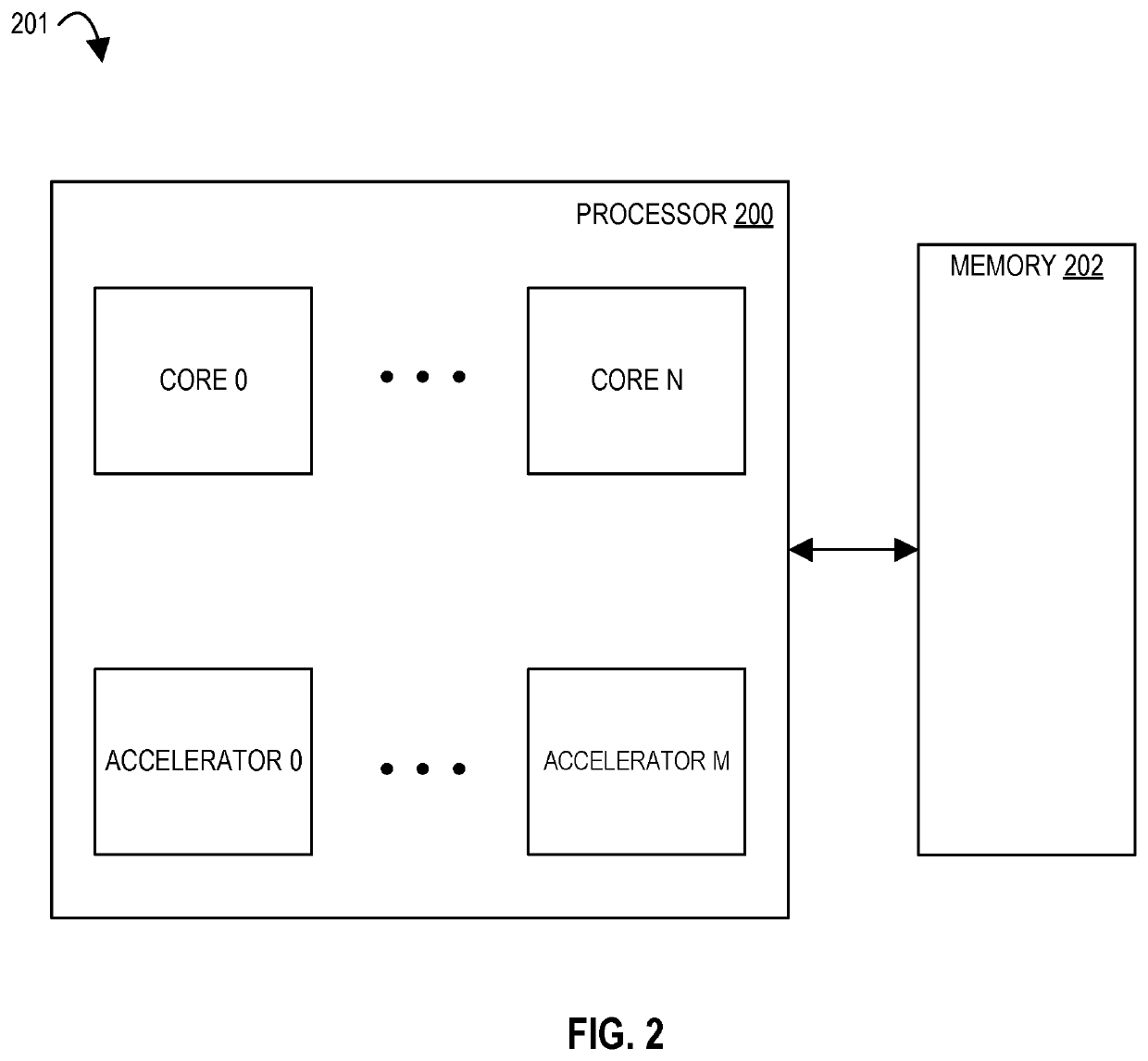
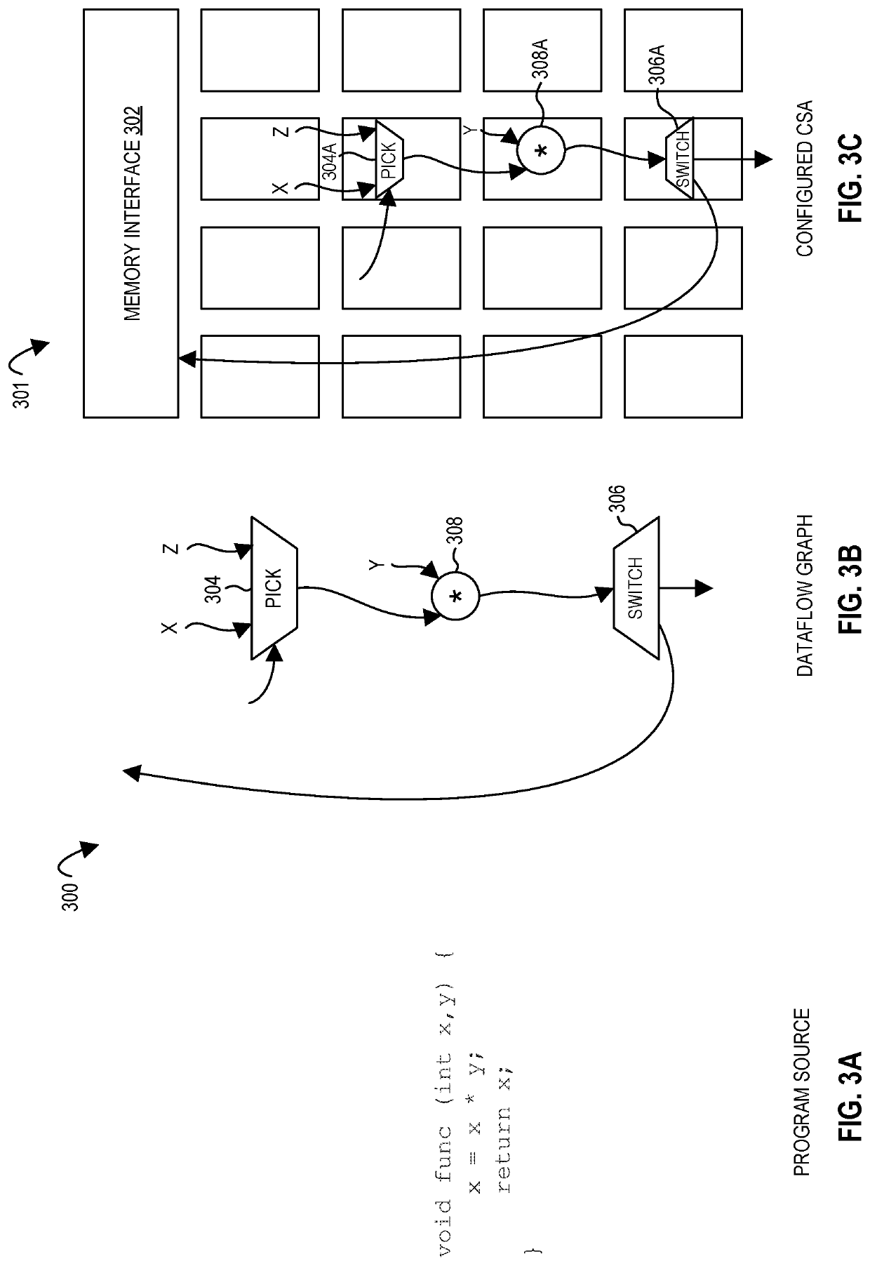
TECHNICAL FIELD[0001]The disclosure relates generally to electronics, and, more specifically, an embodiment of the disclosure relates to time-multiplexing of a network or processing elements of a configurable spatial accelerator.BACKGROUND[0002]A processor, or set of processors, executes instructions from an instruction set, e.g., the instruction set architecture (ISA). The instruction set is the part of the computer architecture related to programming, and generally includes the native data types, instructions, register architecture, addressing modes, memory architecture, interrupt and exception handling, and external input and output (I / O). It should be noted that the term instruction herein may refer to a macro-instruction, e.g., an instruction that is provided to the processor for execution, or to a micro-instruction, e.g., an instruction that results from a processor's decoder decoding macro-instructions.BRIEF DESCRIPTION OF THE DRAWINGS[0003]The present disclosure is illustrat...

Claims


Application Information

Patent Timeline
Patent Type & Authority Applications(United States)
IPC IPC(8): G06F9/30G06F9/38G06F9/445G06F13/40G06F16/901
CPCG06F9/30196G06F9/3885G06F9/44505G06F9/3877G06F13/4022G06F16/9024G06F9/3005G06F15/173G06F15/825
Inventor CHOFLEMING, KERMINSTEELY, JR., SIMON C.DIAMOND, MITCHELL
Owner INTEL CORP
Why Eureka
Eureka Blog
Learn More