Spot welding system and method for adjusting welding-gun closing speed

a welding gun and closing speed technology, applied in the field of spot welding system, can solve the problems of shortening the time required for the pressurizing force applied to the objective workpiece to reach the target value, affecting the quality of welding, and affecting the welding quality of the electrode pair, so as to improve the welding quality, the effect of reducing the welding cycle time and adjusting the closing speed of the electrode pair

Active Publication Date: 2008-12-18
FANUC LTD
View PDF1 Cites 19 Cited by
  • Summary
  • Abstract
  • Description
  • Claims
  • Application Information

AI Technical Summary

Benefits of technology

[0009]It is an object of the present invention to provide a spot welding system including a robot, which can S automatically and readily adjust a closing speed of an electrode pair to an appropriate value, while accommodating the individual structural difference ox characteristic deterioration with age of a welding gun, and thereby can ensure the improvement of welding quality, and the reduction of a welding cycle time, and can also achieve the simplification and acceleration of a system starting-up work.

Problems solved by technology

For example, if the closing speed of the movable electrode is too fast, an overshoot of a pressurizing force applied to the objective workpieces may become too large and thus a welding current may start to be applied in a state where the pressurizing force is not yet sufficiently stabilized at the target value, and, as a result, a welding quality may be degraded.
Further, in this case, the welding gun and the objective workpieces may be damaged.
On the other hand, if the closing speed of the movable electrode is too slow, the time required for the pressurizing force applied to the objective workpieces to reach the target value may become longer, and thus a welding current may start to be applied in a state where the pressurizing force is insufficient, and also welding quality may be degraded.
In either case, a certain level of welding quality can be ensured by configuring the system in such a manner that the welding current starts to be applied after the pressurizing force is stabilized at the target value, but a problem of increasing cycle time may arise.
However, due to the fact that the welding gun, even of an identical type, typically has an individual structural difference in, for example, friction of moving parts, rigidity of components, etc., and a single welding gun is subjected to a deterioration with age in characteristics such as an electrode wear, etc., and therefore, in the above-described closing-speed adjusting technique by the manual work, there are problems in that excessive burdens are imposed on the operator and significant time is required to start up the system.
Further, in the correction of the protruding amount of the movable electrode, a position command is computed while considering the deflection of components provided for the stationary electrode, and therefore, it is required to prepare data of respective welding guns for accommodating the individual structural difference thereof, which makes a system starting-up work complicated.

Method used


Image

  • Spot welding system and method for adjusting welding-gun closing speed
  • Spot welding system and method for adjusting welding-gun closing speed
  • Spot welding system and method for adjusting welding-gun closing speed

Examples


first embodiment

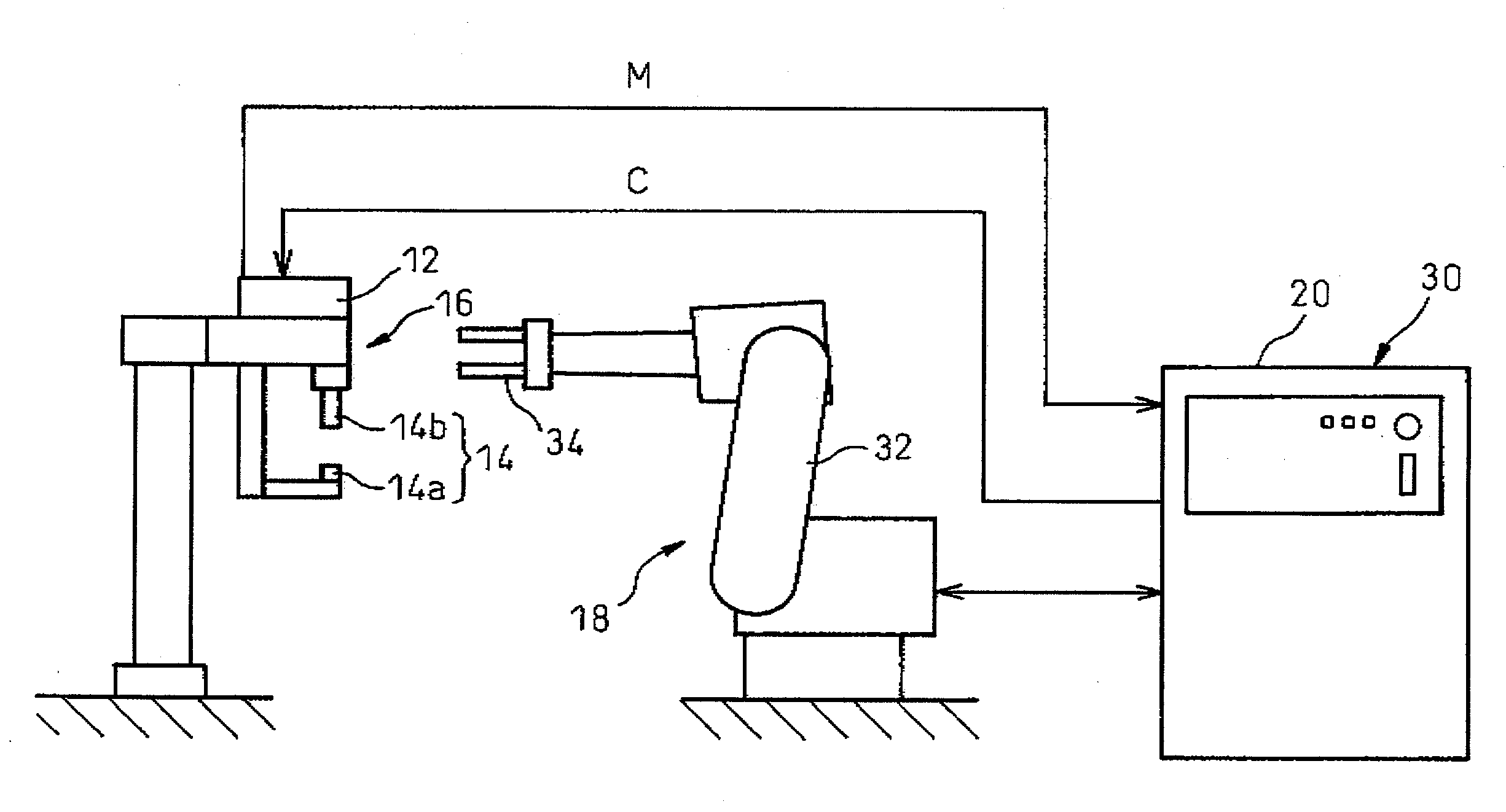
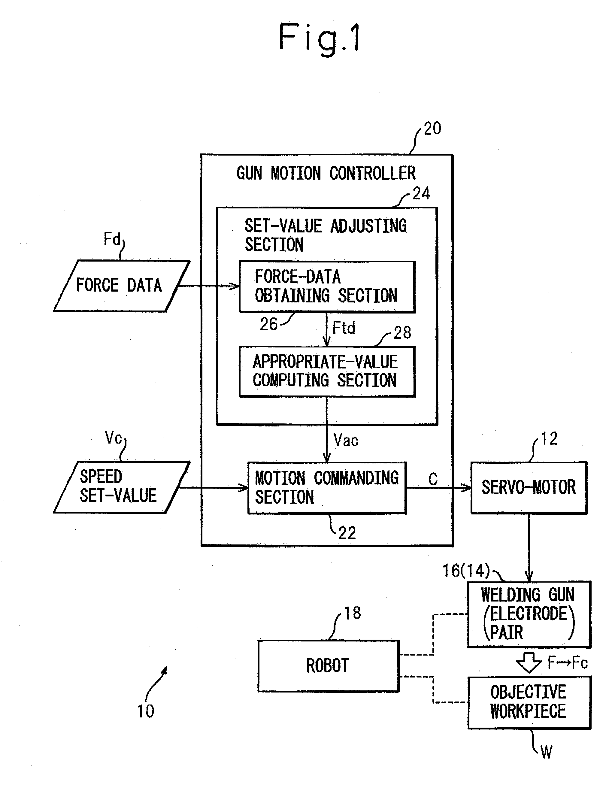
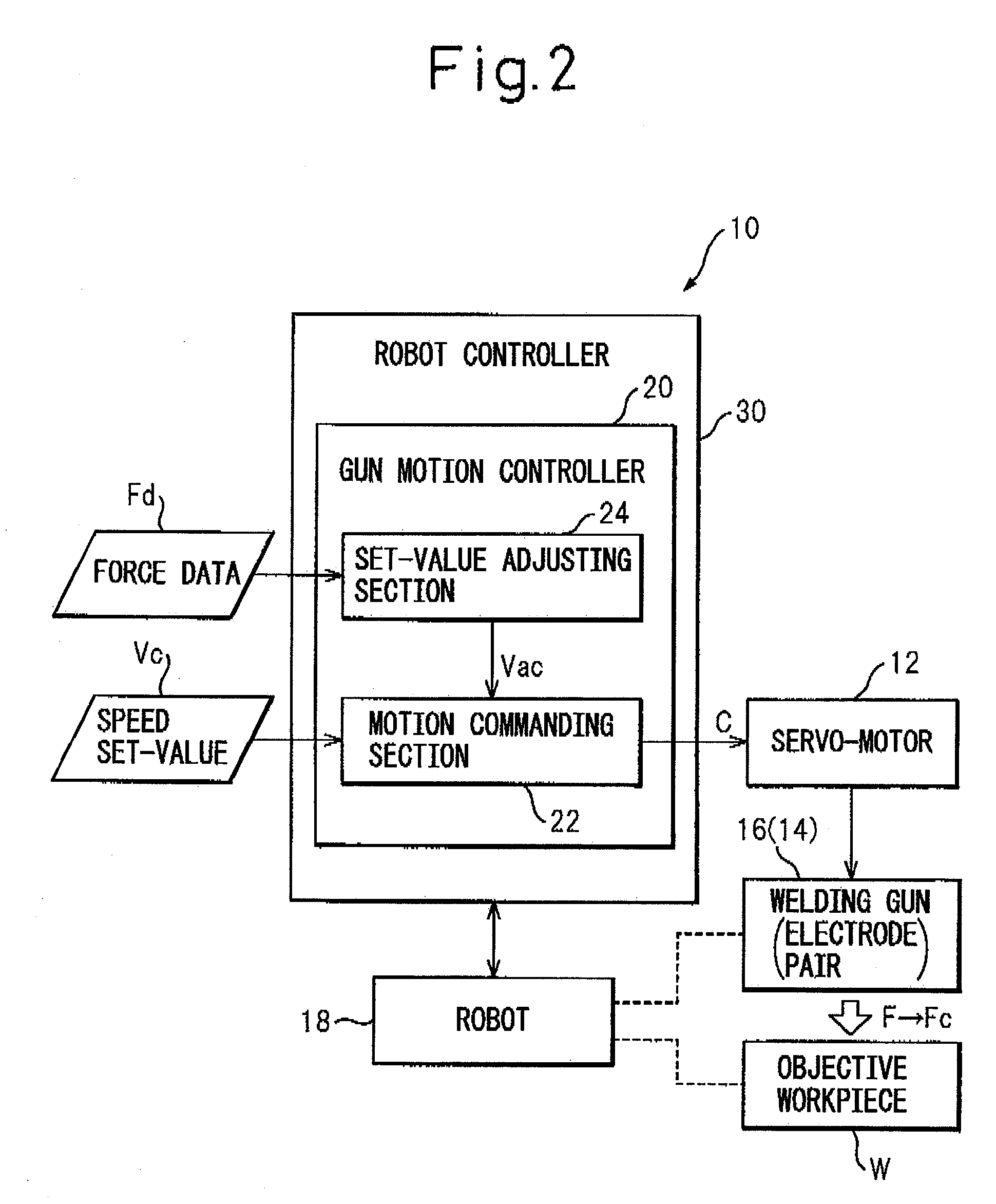
[0052]A configuration of the gun motion controller 20 and a closing-speed automatic adjusting process for the welding gun 16 (FIG. 1) performed by the gun motion controller 20, in the spot welding system according to the present invention, will be described with reference to FIGS. 7 to 9B. The gun motion controller 20 according to the illustrated embodiment has a basic configuration identical to that of the gun motion controller 20 shown in FIG. 1, and therefore, corresponding components are designated by like reference numerals and the descriptions thereof are not repeated.

[0053]As shown in FIG. 7, the gun motion controller 20 includes the motion commanding section 22 and the set-value adjusting section 24, and the set-value adjusting section 24 includes the force-data obtaining section 26 and the appropriate-value computing section 28. In the illustrated embodiment, the appropriate-value computing section 28 includes a representative-value calculating section 56 that calculates, f...

second embodiment

[0069]Now, a configuration of the gun motion controller 20 and a closing-speed automatic adjusting process for the welding gun 16 (FIG. 1) performed by the gun motion controller 20, in the spot welding system according to the present invention, will be described with reference to FIGS. 10 to 14B. The gun motion controller 20 according to the illustrated embodiment has a basic configuration identical to that of the gun motion controller 20 shown in FIG. 1, and therefore, corresponding components are designated by like reference numerals and the descriptions thereof are not repeated.

[0070]As shown in FIG. 10, the gun motion controller 20 includes the motion commanding section 22 and the set-value adjusting section 24, and the set-value adjusting section 24 includes the force-data obtaining section 26 and the appropriate-value computing section 28. In the illustrated embodiment, the force-data obtaining section 26 obtains mutually different several sets (“m” sets) of force data Fd[1] t...


PUM

PropertyMeasurementUnit
pressurizing forceaaaaaaaaaa
speedaaaaaaaaaa
force-aaaaaaaaaa

Abstract

A spot welding system including a welding gun with an electrode pair actuated by a servo-motor, a robot carrying the welding gun or objective workpieces and operating to change the relative positions and orientations of the welding gun and the workpieces, and a gun motion controller controlling the servo-motor to actuate the electrode pair to open or close. The gun motion controller includes a motion commanding section outputting a motion command to the servo-motor in accordance with a speed set-value designating a closing speed of the electrode pair, and a set-value adjusting section automatically adjusting the speed set-value to an appropriate value. The set-value adjusting section includes a force-data obtaining section obtaining force data representing, in a time-series manner, the pressurizing force generated in the electrode pair when the servo-motor actuates the electrode pair to close in accordance with the motion command, and an appropriate-value computing section determining the appropriate value of the speed set-value based on pre-convergence transient data in the force data.

Description

BACKGROUND OF THE INVENTION[0001]1. Field of the Invention[0002]The present invention relates to a spot welding system including a robot. The present invention also relates to a method for adjusting a closing speed of a welding gun, which can be performed in the spot welding system.[0003]2. Description of the Related Art[0004]Spot welding is known as a type of resistance welding technique, in which a plurality of objective workpieces to be welded, are placed on each other and held between a pair of electrodes (referred to as “an electrode pair” in this application) of a welding gun, and a predetermined current is applied to the held points of the objective workpieces during a predetermined period while applying a predetermined pressurizing force to the held points, so as to obtain a weld of a desired quality. The welding gun is typically configured such that a movable-side electrode is actuated to open or close with respect to a stationary-side electrode, and in recent years, a serv...

Claims


Application Information

Patent Timeline
Patent Type & Authority Applications(United States)
IPC IPC(8): B23K11/00
CPCB23K11/252B23K11/253
Inventor TAKAHASHI, HIROMITSUAOKI, TOSHIMICHI
Owner FANUC LTD
Why Eureka
Try Eureka