Surface Mount Type Vibration Motor and Fixation Structure

a vibration motor and surface mount technology, applied in the field of vibration motors, can solve the problems of heavy total weight, difficult to retain the motor body on a plane, and stably install the motor body, and achieve the effects of increasing the strength of bonding, enlarging an area, and stable installation of the vibration motor

Inactive Publication Date: 2008-12-18
NAMIKI PRECISION JEWEL CO LTD
View PDF9 Cites 16 Cited by
  • Summary
  • Abstract
  • Description
  • Claims
  • Application Information

AI Technical Summary

Benefits of technology

[0011]The invention according to claim 1 produces the effect that the end portions of support plates for pedestals of the motor holder prevent the vibration motor body from tilting in the same direction as the downward movement of the center of gravity of the eccentric weight, which enables stable installation of the vibration motor on the circuit board when mounting the vibration motor on the circuit board. In addition, it is possible to allow the support plates to bear an external force generated by the eccentric weight to keep the axis of the output shaft parallel with the circuit board surface.
[0012]The invention according to claim 1 enables the end portions of the support plates to keep the output shaft parallel with the circuit board by arranging the end portions of the support plates in the above-described positions when the vibration motor body is subjected to a force that acts to move the end of the output shaft, namely the eccentric weight, toward the circuit board, for example, a force that acts to allow the vibration motor body to tilt in the same direction as the downward movement of the center of gravity of the eccentric weight.
[0013]At the same time, the invention according to claim 1 results in an effect that a gyrating force generated by rotation of the eccentric weight of the vibration motor is efficiently transmitted to the bonded circuit board to obtain a vibration force during a rotation motion of the vibration motor.
[0014]The invention according to claim 2 increases the strength of the bonding between the surface mount type vibration motor and the circuit board, contributes to enlarging an area to be soldered with the circuit board, and prevents the vibration motor from peeling off the circuit board due to the increase in the bonding strength and a decrease in the influence from the external force.
[0015]The invention according to claim 2 further increases the strength of bonding and stabilization between the surface mount type vibration motor and the circuit board because all areas of the support plates are soldered to the circuit board compared with a vibration motor where the pedestals are partially soldered to the circuit board.
[0016]The invention according to claim 3 results in an effect that an external force transmitted to the vibration motor body is reduced by placing an elastic member between the barrel of the vibration motor body and the motor holder and soldering the pedestals with the circuit board to mitigate the effects of a shock load on the vibration motor body from being dropped, thus preventing the surface mount vibration motor from peeling off the circuit board due to a large shock load.

Problems solved by technology

On the other hand, a surface mount type vibration motor larger in size than other electronic parts with an eccentric weight and a high specific gravity results in a heavy total weight.
In addition, a longitudinal dimension of a vibration motor body must be reduced to satisfy the requirement for size reduction for a mounted device, and when mounting on a circuit board surface, an extremely heavy eccentric weight attached to an output shaft causes an imbalance depending on a shape of a motor holder, further making it difficult to retain the motor body on a plane.
Therefore, the center of gravity of the motor body with an attached eccentric weight deviating to the weighted side makes it difficult to stably install the motor body, creating the possibility that the body will tilt in the same direction as the downward movement of the center of gravity of the eccentric weight due to a small vibration during movement inside a solder reflow furnace.
Moreover, after the solder reflow process, if a mobile phone or similar electronic device is dropped, the parts of the vibration motor are subjected to a shock load in proportion to the mass of the eccentric weight.
Therefore, the resulting potential problem is peeling of the soldered portion from the shock compared with other lighter electronic parts.
In addition to the shock load from being dropped, when a gyrating force of the eccentric weight is large, the solder bonded surface may be affected over time, thus it is necessary to develop a shape or a structure of the motor holder for bonding the motor body wherein the motor body will tend to tilt due to the centrifugal force of the rotating eccentric weight.

Method used


Image

  • Surface Mount Type Vibration Motor and Fixation Structure
  • Surface Mount Type Vibration Motor and Fixation Structure
  • Surface Mount Type Vibration Motor and Fixation Structure

Examples


Embodiment Construction

[0019]The preferred embodiments of a surface mount type vibration motor according to this invention is hereafter described while referring to drawings.

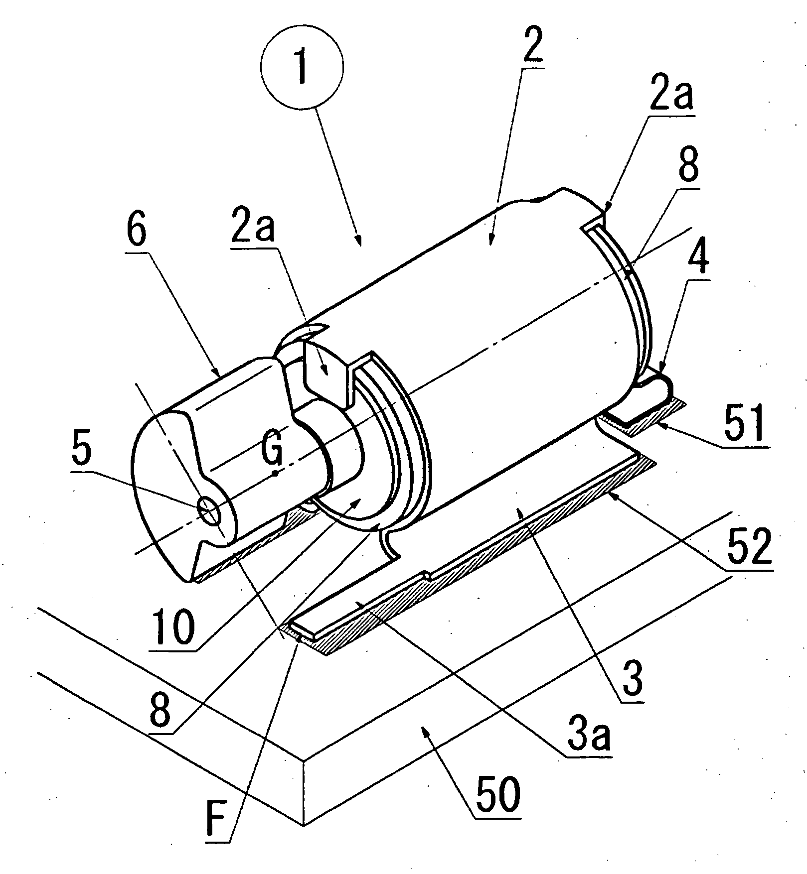
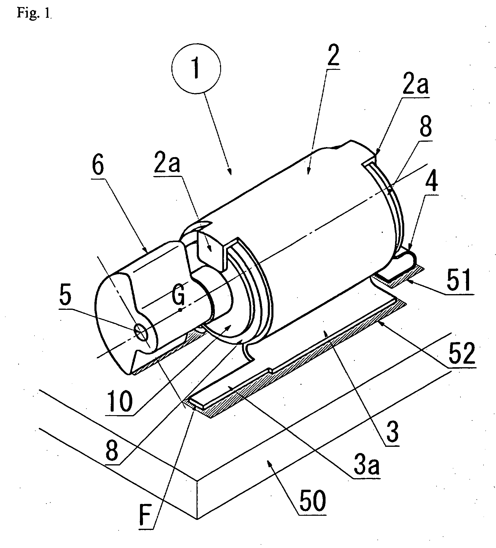
[0020]A surface mount type vibration motor 1 according to this embodiment shown in FIGS. 1 and 2 is a surface mount component reflow soldered on a circuit board 50 with a bonding section printed with cream solder. This surface mount type vibration motor 1 comprises an eccentric weight 6, an almost cylindrical motor barrel 10 enclosing a vibration motor body, and a motor holder 2 for holding the motor barrel 10.

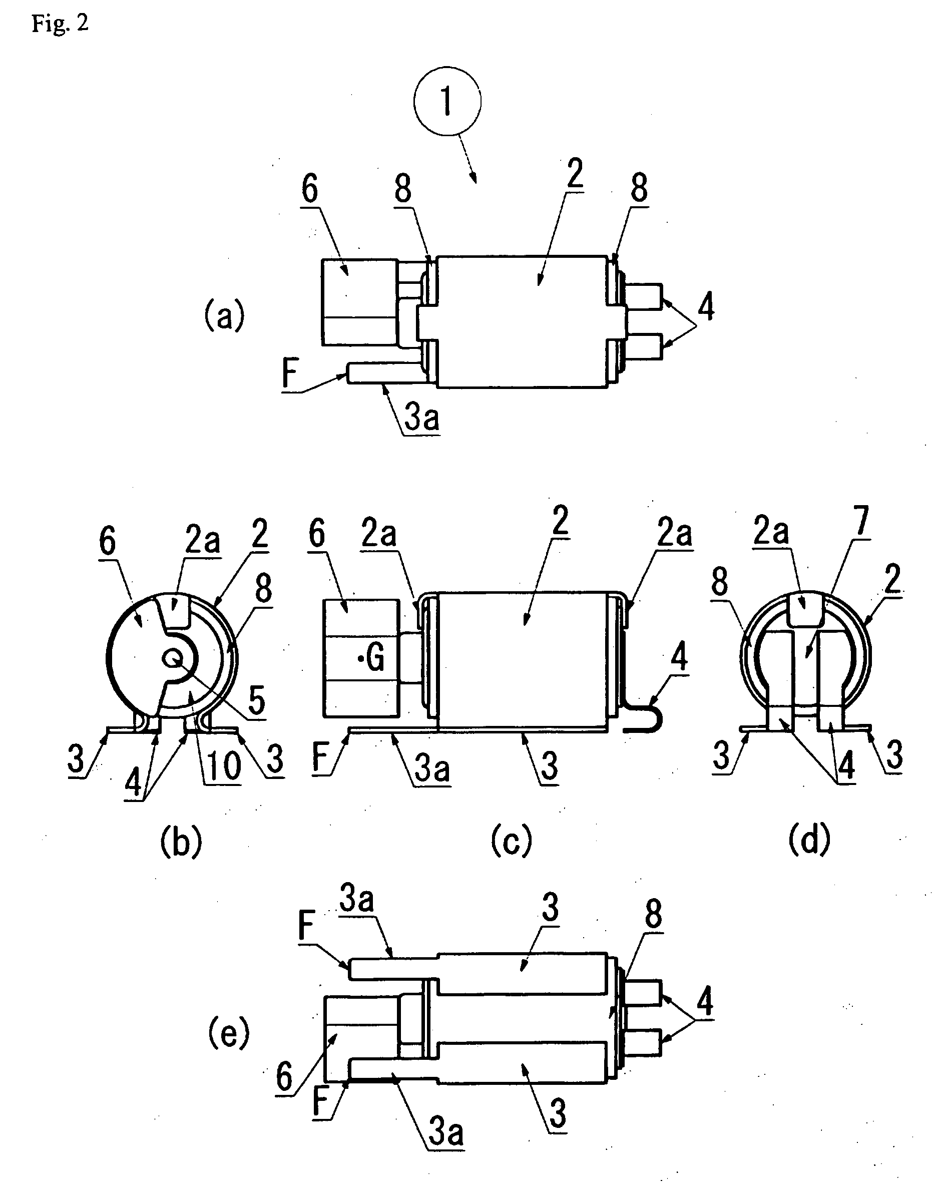
[0021]The eccentric weight 6 is attached to an output shaft 5 of the motor body with an almost fan-like cross section in a plane perpendicular to the axis of the output shaft 5 as shown in the drawings.

[0022]Another end of the motor barrel 10 is attached with an end bracket 7 as shown in FIG. 2 (d), and an outer surface of this end bracket 7 is provided with a pair of power supply terminals 4 electrically connected to brush piec...


PUM


Abstract

In a solder reflow process, a vibration motor is stably mounted on a circuit board by changing the design of a partial shape of a soldered motor holder without changing the design of a vibration motor body and securing a sufficient soldering area to completely perform solder bonding to prevent a soldered portion of a motor holder from peeling off the circuit board.
[Solution] To provide a surface mount type vibration motor, wherein the pedestals of a motor holder comprise the support plates that are in contact with stationary lands on a surface of a circuit board and extend in the axial direction of an output shaft, end portions of the support plates are arranged between the position of an eccentric weight and the end surface of the eccentric weight along the axial direction, and the support plates are not arranged just under an axis of said output shaft where the distance between the weight and the circuit board is minimum.

Description

TECHNICAL FIELD[0001]This invention relates to a vibration motor applicable to a solder reflow process, more specifically a surface mount type vibration motor provided with a motor holder made of metal and soldered to a circuit board.BACKGROUND ART[0002]Many small surface mount type electronic parts applicable to a solder reflow process are conventionally adopted as circuit parts mounted on electronic devices. Each of these small electronic parts is placed in a specified location on a circuit board printed with cream solder by a mounting device and collectively heat treated in a furnace for installation on a circuit board with molten solder.[0003]In a manner similar to the above electronic parts, a vibration generation device (hereafter referred to as “vibration motor”) used for mobile phones is also installed in a specified location on a circuit board by a solder reflow process, and a surface mount type vibration motor is attracting attention as a device applicable to the reflow pr...

Claims


Application Information

Patent Timeline
Patent Type & Authority Applications(United States)
IPC IPC(8): H02K7/075
CPCB06B1/16H02K7/061H05K3/301H05K3/341H05K2201/1009H05K2201/10325H05K2201/10606H02K5/22H02K7/075
Inventor SUZUKI, TOSHIOAOYAGI, TOMOHIDEKOGAWA, TAKESHI
Owner NAMIKI PRECISION JEWEL CO LTD
Why Eureka
Try Eureka