
Spark plug and method for production of a spark plug

a technology of spark plugs and spark plugs, which is applied in the manufacture of spark plugs, spark plugs, machines/engines, etc., can solve the problems of limiting the service life of spark plugs, increasing the risk of shunt formation, and gas leakage out of combustion chambers through inadequate sealing areas of spark plugs, so as to meet the high demands placed on spark plugs more efficiently

Inactive Publication Date: 2008-12-18
FEDERAL MOGUL IGNITION +1
View PDF14 Cites 10 Cited by
  • Summary
  • Abstract
  • Description
  • Claims
  • Application Information

AI Technical Summary

Benefits of technology

The invention is about making spark plugs more efficiently by using an extruded insulator body. This allows for smaller thread sizes, which is important for racing engines and similar applications where space is limited. The use of an inner conductor and insulator body produced jointly by co-extrusion helps save costs and eliminates leakage points between the two. The use of an electrically conductive ceramic material for the inner conductor helps achieve higher mechanical strength and allows for easy adjustment of suppression resistance. Plasticizers can be added to the ceramic materials to make them easier to shape and sinter. The materials used for the inner conductor include silicides, carbides, nitrides, and / or borides, and non-oxide ceramic materials based on carbides, nitrides, and / or borides of metals like silicon, aluminum, or titanium are particularly well-suited for co-extrusion with the insulator body. Al2O3 or a composite of Al2O3 with LaCrO3 or TiN can also be used for the insulator body.

Problems solved by technology

Under the effect of high peak pressures it may happen, even with plugs that have been produced accurately to size and have been carefully sealed, that gases leak out from the combustion chamber via inadequately sealed areas of the spark plug.
Such leakage gases, which may enter the interior of the plug along boundary surfaces between the central electrode and the insulator body, or the inner conductor and the enclosing insulator body, may produce deposits in the interior of the spark plug which increase the risks of shunts forming, thereby limiting the service life of a spark plug.

Method used


Image

  • Spark plug and method for production of a spark plug
  • Spark plug and method for production of a spark plug
  • Spark plug and method for production of a spark plug

Examples


Embodiment Construction

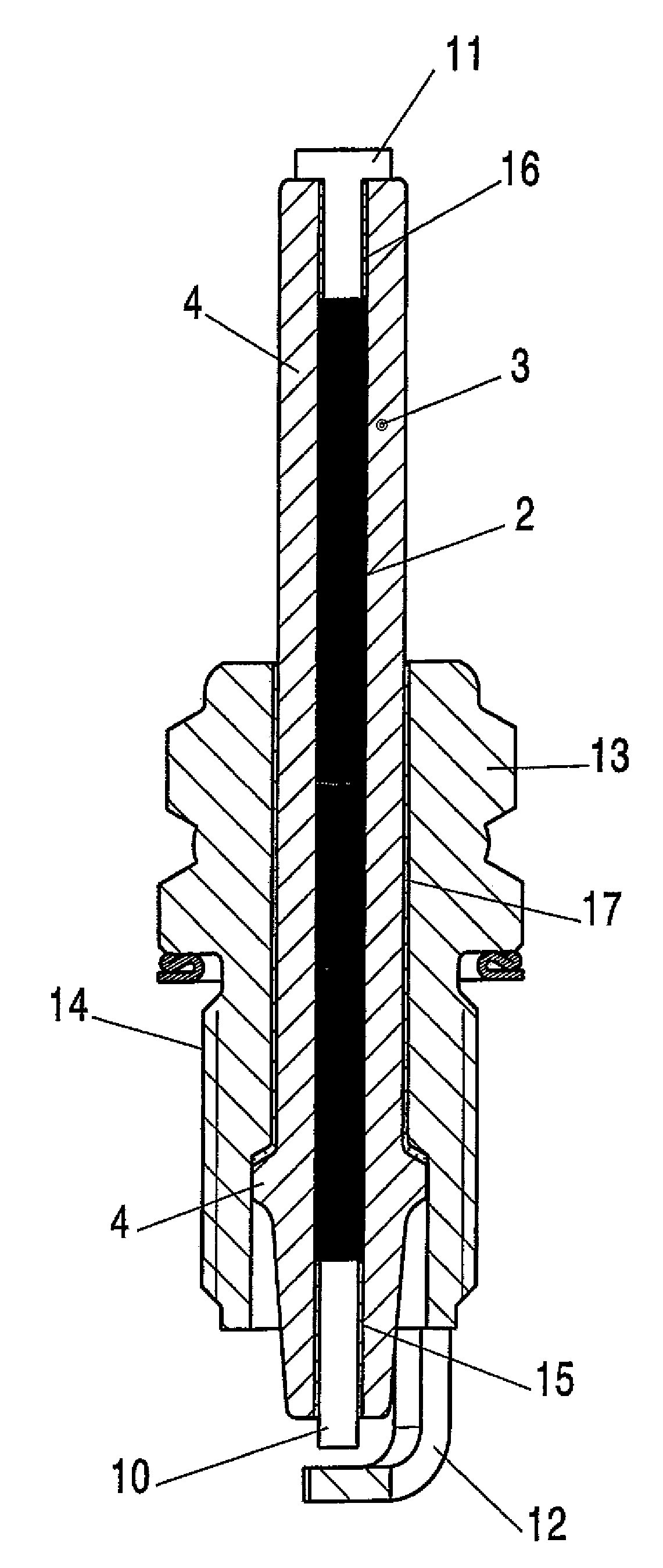
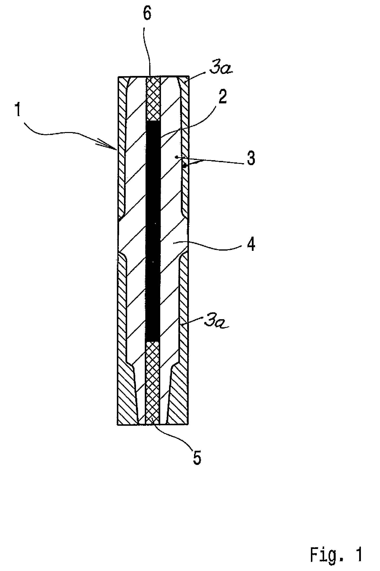
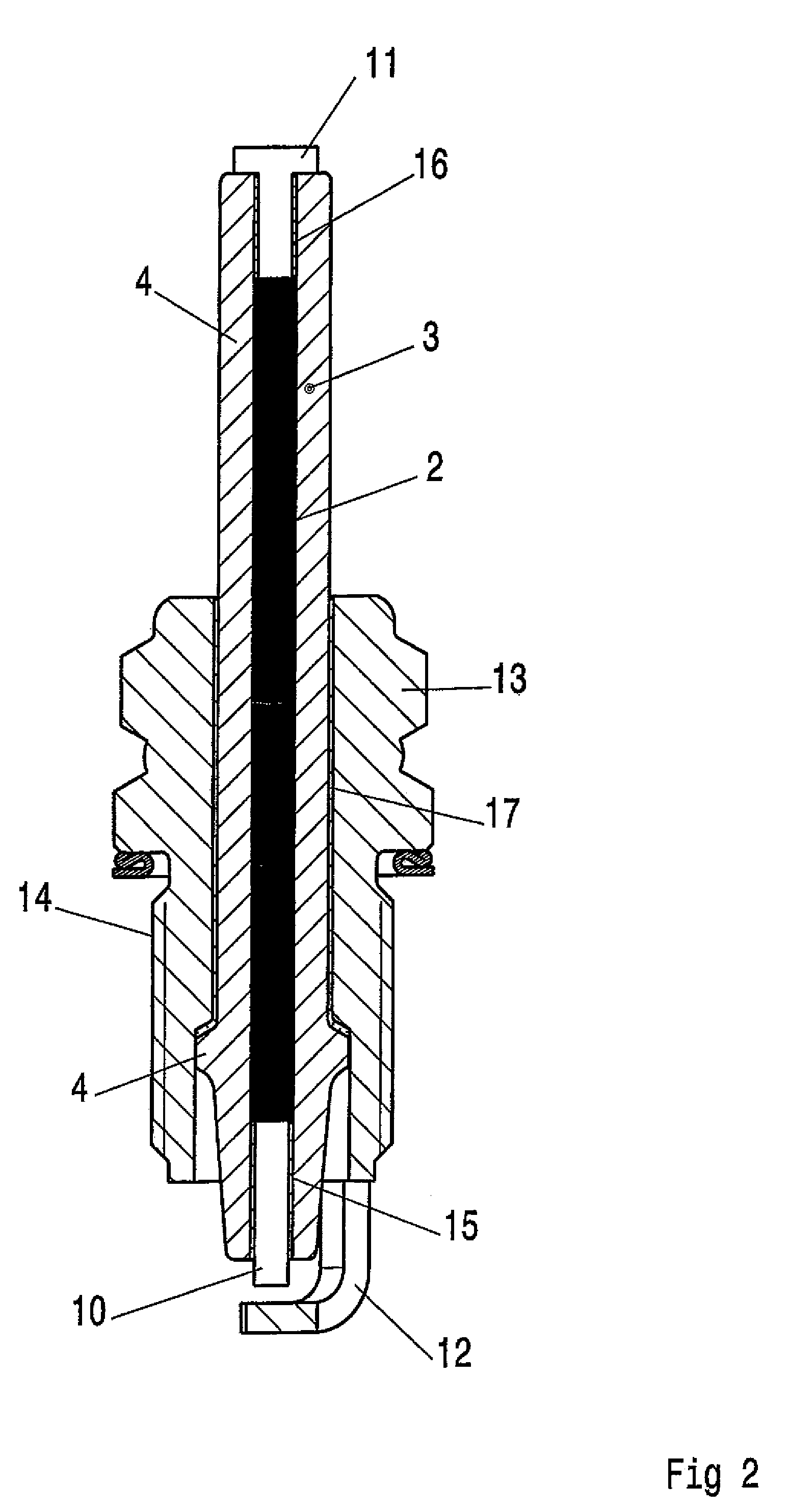
[0014]FIG. 1 shows a co-extruded green compact 1 of cylindrical shape, comprising an electrically conductive ceramic material 2 intended to form an inner conductor at its center, and an electrically insulating ceramic material 3 enclosing the inner conductor 2. The co-extruded green compact 1 constitutes a semi-finished product for the production of a spark plug. The green compact 1 is given the length desired for a spark plug, and its outer contour is shaped so that the electrically insulating ceramic material 3 assumes the contour with a collar 4 usual for a spark plug. The outer areas 3a of the green compact 1 that are to be removed by shaping operations, for example by lathe cutting or grinding, are shown as hatched areas in FIG. 1. Due to the plasticity required for the co-extrusion process, the green compact 1 can be worked relatively easily. A hard, mechanically strong ceramic body comprising a crystalline inner conductor 2 and an insulator 3 enclosing the inner conductor are...


PUM


Abstract

The invention describes a spark plug having an outer electrode (12), a central electrode (10), an inner conductor (2) connected to the central electrode (10) and an insulator (3) enclosing the inner conductor (2). It is provided according to the invention that the insulator (3) is produced by extrusion. The invention further relates to a method for production of a spark plug of that kind.

Description

[0001]The present invention relates to a spark plug for use in combustion engines, having an outer electrode, a central electrode, an inner conductor connected to the central electrode and an insulator body enclosing the inner conductor, and to a method for production of a spark plug of that kind.[0002]In operation spark plugs are subjected to pressure and temperature conditions that place exacting demands on the mechanical strength of the insulator body and the sealing of the boundary surfaces between different plug elements, relative to the combustion chamber of an engine. Under the effect of high peak pressures it may happen, even with plugs that have been produced accurately to size and have been carefully sealed, that gases leak out from the combustion chamber via inadequately sealed areas of the spark plug. Such leakage gases, which may enter the interior of the plug along boundary surfaces between the central electrode and the insulator body, or the inner conductor and the en...

Claims


Application Information

Patent Timeline
Patent Type & Authority Applications(United States)
IPC IPC(8): H01T13/38H01T21/02
CPCH01T13/38H01T21/02
Inventor NIESSNER, WERNERFRASSEK, LUTZHOUBEN, HANS
Owner FEDERAL MOGUL IGNITION
Learn More