Cooling apparatus for fuel cell

a fuel cell and cooling apparatus technology, applied in the direction of fuel cells, solid electrolyte fuel cells, cell components, etc., can solve the problems of high labor charge reduce and restrain the conductivity of the cooling medium

Inactive Publication Date: 2008-12-18
TOYOTA JIDOSHA KK
View PDF1 Cites 4 Cited by
  • Summary
  • Abstract
  • Description
  • Claims
  • Application Information

AI Technical Summary

Benefits of technology

[0006]The present invention adopts the following means in order to solve the problems given above. Namely, the present invention is a cooling apparatus for a fuel cell, comprises cooling piping through which a cooling medium for cooling the fuel cell flows, a conductivity measuring unit measuring a conductivity of the cooling medium that flows through the cooling piping, a conductivity reducing agent supply unit supplying the cooling piping with a conductivity reducing agent for reducing the conductivity of the cooling medium, and a control unit controlling the conductivity reducing agent supply unit in accordance with a value of the measured conductivity. According to the present invention, whether the supply of the conductivity reducing agent to the cooling piping is required or not is determined based on a value of the conductivity of the cooling medium flowing through the cooling piping. Then, when the supply of the conductivity reducing agent to the cooling piping is required, the conductivity reducing agent is supplied to the cooling piping. This scheme enables a decrease in the conductivity of the cooling medium flowing through the cooling piping and enables the conductivity of the cooling medium to be restrained from rising.
[0007]The control unit, when the value of the measured conductivity is equal to or larger than a predetermined value, may control the conductivity reducing agent supply unit to supply the cooling piping with the conductivity reducing agent. When the value of the conductivity measured by the conductivity measuring unit is equal to or larger than the predetermined value, the cooling piping is supplied with the conductivity reducing agent. With this scheme, if the conductivity of the cooling medium flowing through the cooling piping is equal to or larger than the predetermined value, it is possible to reduce the conductivity of the cooling medium flowing through the cooling piping and to restrain the rise in the conductivity of the cooling medium.
[0008]The conductivity reducing agent may have a hydroxy group. When the cooling piping is supplied with the conductivity reducing agent, the ions contained in the cooling medium flowing via the cooling piping are embraced by the hydroxy groups possessed by the conductivity reducing agent. This scheme enables the decrease in the conductivity of the cooling medium flowing through the cooling piping and enables the conductivity of the cooling medium to be restrained from rising.
[0009]The cooling piping may have a protruded portion inwardly. An ion substance produced by embracing the ions with the hydroxy groups possessed by the conductivity reducing agent resides on the protruded portion provided inwardly of the cooling piping. This scheme enables the ion substance to be restrained from flowing within the cooling piping and a flow of the cooling medium flowing through the cooling piping to be maintained.
[0010]The cooling apparatus for a fuel cell may further comprise a discharge valve for discharging the cooling medium flowing via the cooling piping, wherein the control unit may, after controlling the conductivity reducing agent supply unit to supply the cooling piping with the conductivity reducing agent, control the discharge valve to discharge the cooling medium flowing via the cooling piping if a predetermined period of time elapses. The cooling piping is supplied with the conductivity reducing agent and, when the predetermined period of time elapses, the cooling medium flowing through the cooling piping is discharged. Then, the ion substance reserved on the protruded portion within the cooling piping is discharged outside the cooling piping. With this scheme, the ion substance reserved on the protruded portion can be restrained from overflowing from on the protruded portion, whereby the hydroxy groups can be restrained from being decoupled from the ions. As a result, the rise in the conductivity of the cooling medium can be restrained.
[0011]According to the cooling apparatus of the present invention, the rise in the conductivity of the cooling medium can be restrained.

Problems solved by technology

Further, a complicated operation for exchanging the ion exchanger is periodically needed, and hence a high labor charge occurs.

Method used


Image

  • Cooling apparatus for fuel cell
  • Cooling apparatus for fuel cell
  • Cooling apparatus for fuel cell

Examples


first embodiment

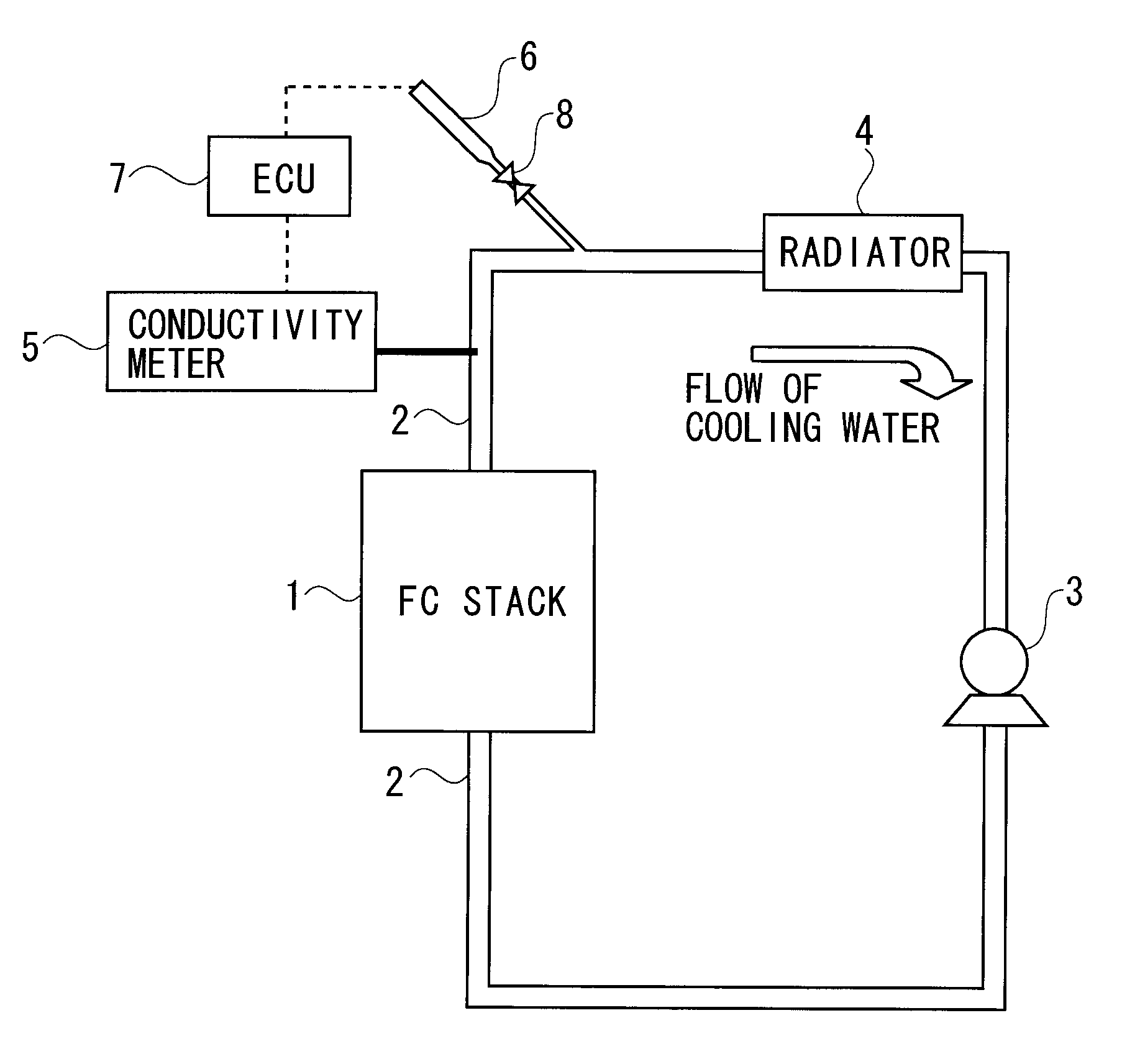
[0022]A cooling system according to a first embodiment will hereinafter be described with reference to FIGS. 1 through 6. FIG. 1 is a diagram showing an example of a configuration of the cooling system of a fuel cell mounted on a mobile object such as mainly a fuel cell vehicle.

[0023]In FIG. 1, the cooling system according to the first embodiment includes a fuel cell stack 1, cooling system piping 2 via which cooling water circulates, a water pump 3 that circulates the cooling water, a radiator 4 that radiates heat of the cooling water into an outside air, a conductivity meter 5 for measuring a conductivity (an electrical conductivity) of the cooling water, a syringe 6 that injects a water solution into the cooling system piping 2, and an electronic control unit (ECU) 7 that is electrically connected to the conductivity meter 5 and to the syringe 6. In the first embodiment, the cooling water is circulated through the cooling system piping 2, however, in addition to the cooling water...

second embodiment

[0052]Next, the cooling system according to a second embodiment will be described. The same portions as those in the first embodiment discussed above are marked with the same numerals and symbols, and their detailed descriptions are omitted. In the cooling system according to the second embodiment, as illustrated in FIG. 7, the cooling system piping 2 is provided with a discharge pipe 20, and the discharge pipe 20 is provided with a discharge valve 21. The discharge pipe 20 is provided substantially in parallel with the angle of the gradient of the protruded portion 10. Then, the surface of the protruded portion 10 is connected to part of the inner wall surface of the discharge pipe 20. In FIG. 7, the discharge pipe 20 and the discharge valve 21 are provided on a one-by-one basis with respect to the protruded portion 10 and may also be provided on a plurality-by-plurality basis with respect to the protruded portion 10.

[0053]The electronic control unit 7 is electrically connected to ...

modified example

[0065]In the second embodiment, the large molecules residing on the protruded portion 10 provided on the inner wall surface of the cooling system piping 2 flow to the discharge pipe 20 and are discharged outside the cooling system piping 2. In the present modified example, an acid substance (e.g., acetic acid etc) is flowed to the cooling system piping 2, and the large molecules are hydrolyzed, whereby the large molecules residing on the protruded portion 10 provided on the inner wall surface of the cooling system piping 2 may be removed. In this case, the cooling system piping 2 is detached from the cooling system and may be washed with the acid substance.


PUM

PropertyMeasurementUnit
angleaaaaaaaaaa
conductivity measuringaaaaaaaaaa
conductivityaaaaaaaaaa

Abstract

To provide a cooling apparatus that restrains a rise in conductivity of a cooling medium. A cooling apparatus for a fuel cell includes cooling piping through which a cooling medium for cooling the fuel cell flows, a conductivity measuring unit measuring a conductivity of the cooling medium that flows through the cooling piping, a conductivity reducing agent supply unit supplying the cooling piping with a conductivity reducing agent for reducing the conductivity of the cooling medium, and a control unit controlling the conductivity reducing agent supply unit in accordance with a value of the measured conductivity.

Description

BACKGROUND OF THE INVENTION[0001]The present invention relates to a cooling apparatus for a fuel cell that produces water when generating power.[0002]If a fuel cell system is employed for a long period of time, ions get eluted into a cooling medium (e.g., cooling water, a cooling liquid, a cooling system coolant) from within cooling system piping, a radiator and the fuel cell. An electrical conductivity of the cooling medium consequently rises, and there is a possibility that an electric leak occurs. For ensuring safety, the ions eluted into the cooling system piping are trapped (accumulated up) by disposing an ion exchanger in the cooling system piping, thus restraining the electrical conductivity from rising.[0003][Patent document 1] Japanese Unexamined Patent Application Publication No. 2005-209435[0004][Patent document 2] WO 2003 / 094271SUMMARY OF THE INVENTION[0005]In the case of disposing the ion exchanger in order to restrain the rise in the electrical conductivity of the cool...

Claims


Application Information

Patent Timeline
Patent Type & Authority Applications(United States)
IPC IPC(8): H01M8/04
CPCH01M8/04029H01M8/04044H01M8/04656H01M8/04813Y02E60/50
Inventor INOUE, MASAHIRO
Owner TOYOTA JIDOSHA KK
Why Eureka
Try Eureka