Spinal and Upper Cervical Impulse Treatment and Device

a technology for treating devices and upper cervical spines, applied in non-surgical orthopedic devices, medical science, chiropractic devices, etc., to achieve the effects of enhancing the ease of use of the over-all system, improving accuracy, and superior means of applying force for chiropractic adjustments

Active Publication Date: 2008-12-18
KHAN ASLAM
View PDF13 Cites 12 Cited by
  • Summary
  • Abstract
  • Description
  • Claims
  • Application Information

AI Technical Summary

Benefits of technology

[0016]The spinal and upper cervical impulse treatment device consists of a controller mounted on top of an impulse delivery mechanism, or device head, which is mounted, in turn, on a movable armature attached to a fixed stand. The device head may be rotated or tilted and located freely in three dimensions. At the base of the device head, there is a collapsible stylus or rod, which is used to deliver sinusoidal waveforms of varying frequency and intensity. The impulse waveforms can be delivered along both the linear axis of the stylus and in a rotational direction. Since the device head is fixed in location, a collapsible rod provides a necessary element of safety to the patient.
[0017]Importantly, the spinal and upper cervical impulse treatment device has built-in data validation, so that operation may not commence, until proper alignment of the device head is achieved. This is superior to a situation where correct alignment relies on human recognition of visual feedback mechanisms and operation may be triggered at any time. Accuracy is further improved by use of a digital controller and precision voice coil actuators, rather than components with variable output behavior, like solenoids. The linear force delivered is sinusoidal, and does not have the overshoot, bounce or harmonic characteristics of square waves, and, therefore, is a superior means of applying force for chiropractic adjustments.
[0018]Optionally, impulse control parameters may be transferred to the device in an automated fashion from a remote computer data source. Direction vectors are determined by a practitioner from examination of patient x-rays. Data may be input to the computer system by means of a graphics tablet, where the latter is used to digitize input data that is used to calculate direction vectors. Such automation further enhances the ease of use of the over-all system, as well as contributing to accuracy, consistency, and reliability in treatment protocols.

Problems solved by technology

Importantly, the spinal and upper cervical impulse treatment device has built-in data validation, so that operation may not commence, until proper alignment of the device head is achieved.

Method used


Image

  • Spinal and Upper Cervical Impulse Treatment and Device
  • Spinal and Upper Cervical Impulse Treatment and Device
  • Spinal and Upper Cervical Impulse Treatment and Device

Examples


Embodiment Construction

Device Mounting and Device Head Components

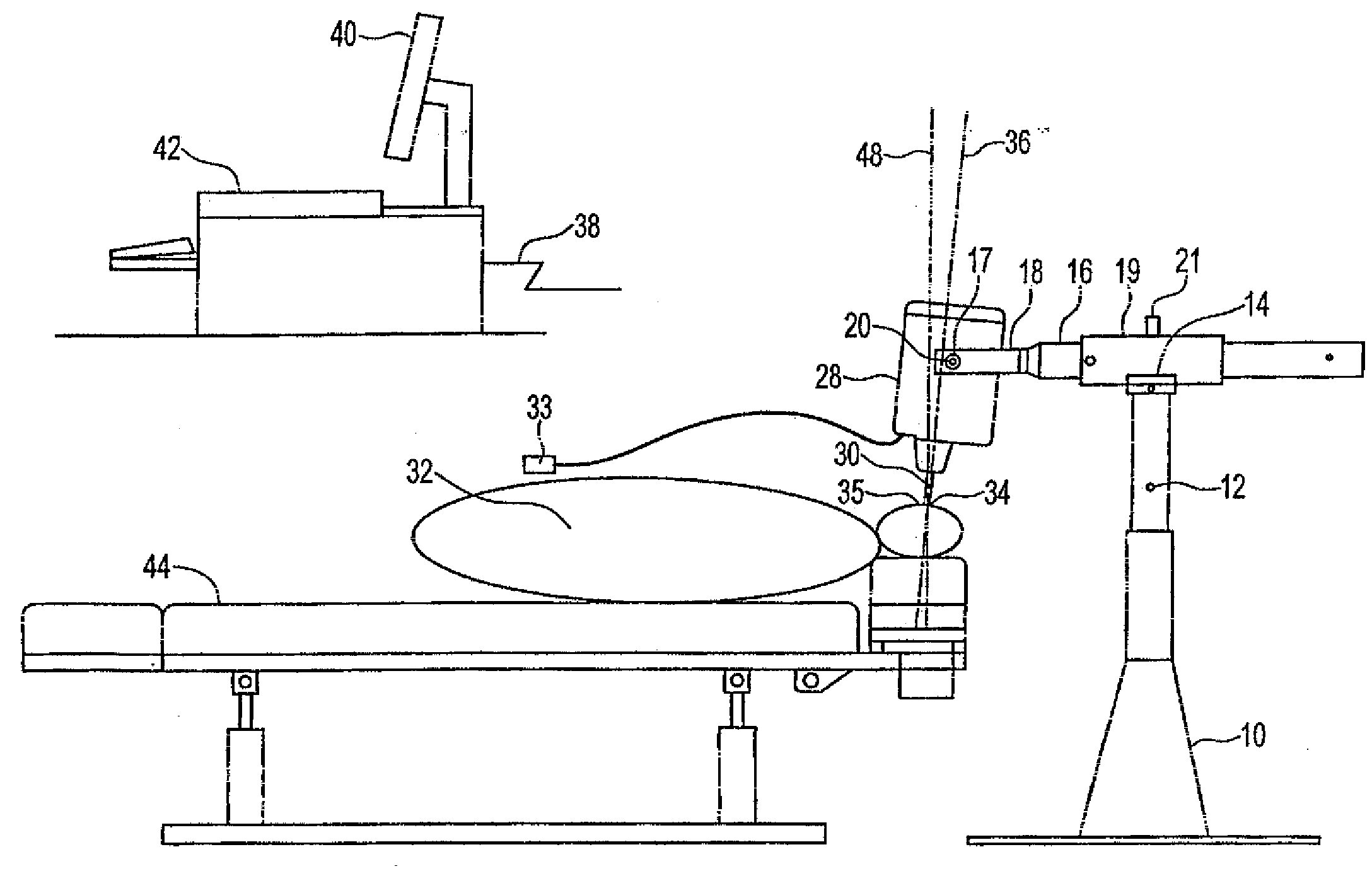
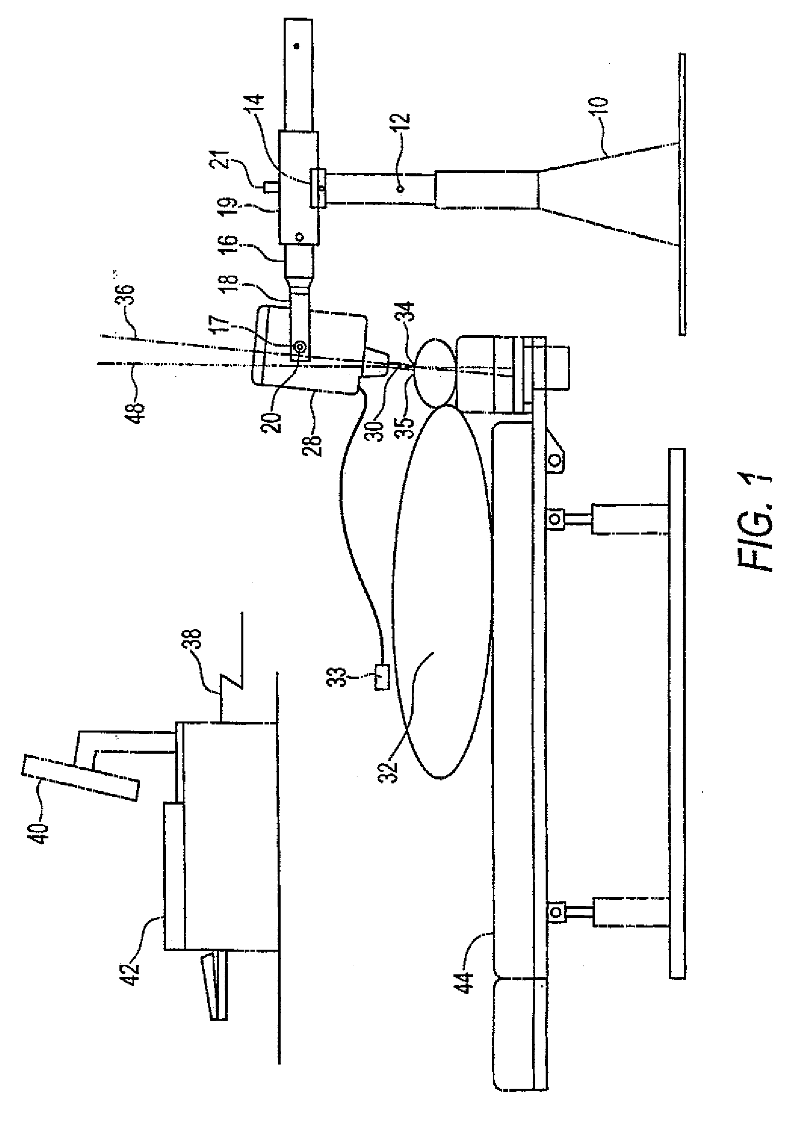
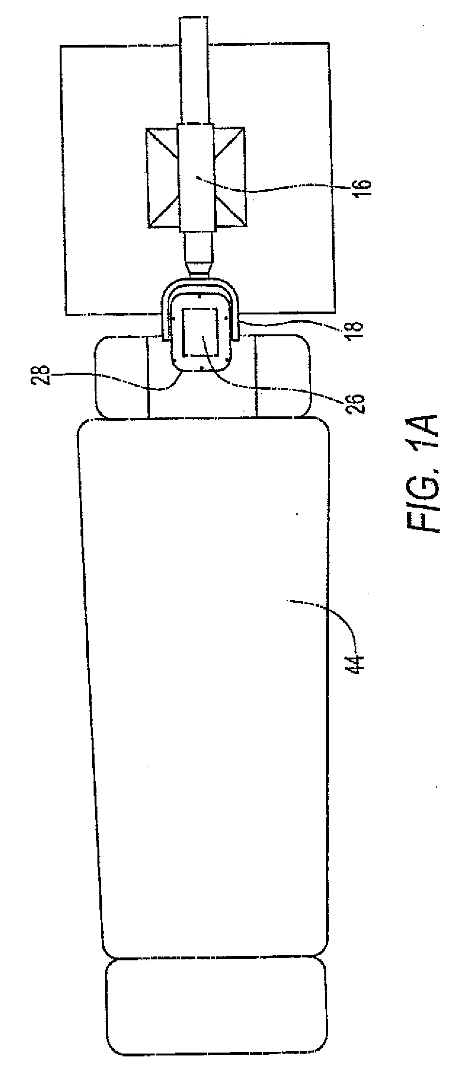
[0031]As shown in FIG. 1, a stable stand 30 supports an arm or armature component 16, which in turn supports the impulse treatment device head 28. Arm 16 is slidably enclosed by sleeve 19. The stand 10 can raise or lower the arm 16 by a large retractable piston or linear actuator 12 that is operator controlled. The arm 16 is mounted at the top of the stand's piston 12 at a complex joint with three degrees of freedom, called the stand coupling 14. The stand coupling 14 allows the arm 16 to rotate in a horizontal plane, creating a yaw angle. Where did this come from? The transducer head can tilt in this direction but the arm cannot. Last, the stand coupling 14 allows a tilt of the aim 16 off the horizontal plane, creating a roll angle. The aim 16 slides forward and back in sleeve 19 relative to the stand 10. Releasing a lock 21 allows arm 16 to rotate within sleeve 19. A groovein arm 16 and a biased ball bearing in the interior cylindrical sur...


PUM


Abstract

The current invention is a spinal and upper cervical impulse treatment device and controller, which delivers multiple impulses of variable frequency and variable force in a linear direction, as well as rotational forces, for patient treatment. Known chiropractic impulse devices are all hand held devices. In contrast, the spinal and upper cervical impulse treatment device is mounted on a fixed stand and armature, allowing reliable positioning and directional alignment in three dimensions. Fixed mounting also facilitates ease of use. A safety coupling is incorporated to avoid patient injury due to excessive force on the treatment site in the fixed mounting scenario Smooth sinusoidal waveforms are a preferred waveform for impulse delivery and sine waves are generated digitally in the apparatus. Data validation is used to ensure correct directional alignment prior to device activation Patient safety and consistency in treatment protocols are considered in the spinal and upper cervical impulse treatment design

Description

FIELD[0001]The current invention comprises a spinal and upper cervical impulse treatment device designed from the overall perspective of minimizing potential harm to the patient and at the same time maximizing the efficacy of treatment to the patient, through the creation of predefined, accurate and repeatable operations. The general mode of treatment is delivery of linear and rotational impulses to a patient's body. These impulses are generated by a transducer component, which has been designed as an element of an integrated system.BACKGROUND[0002]U.S. Pat. No. 4,461,286 issued to Sweat describes a percussive device operated by a trigger. It is capable of delivering a single impulse via a thrust pin, where the force of the impulse is stored in a spring. The spring and thrust pin are housed in a hand held device. The handheld device is positioned manually by a practitioner, both in location and direction. The location of the point of contact on the patient's body and the direction o...

Claims


Application Information

Patent Timeline
Patent Type & Authority Applications(United States)
IPC IPC(8): A61N1/00A61B19/00A61F5/00A61H1/00A61H23/02
CPCA61H1/008A61H2201/5007A61H2201/1669A61H1/00A61H23/02
Inventor KHAN, ASLAMWISHART, PETER
Owner KHAN ASLAM
Why Eureka
Try Eureka