Screw tightening apparatus

a screw and tightening technology, applied in the direction of wrenches, metal-working apparatus, measuring torque/twisting force while tightening, etc., can solve the problem of difficult to precisely form a key groove on the output shaft, the transmission of sufficient torque from the hollow gear may be impossible, and the pitch of the screw is narrower. , to achieve the effect of convenient processing, good conductivity and sufficient torqu

Inactive Publication Date: 2008-12-25
FUJITSU LTD
View PDF1 Cites 22 Cited by
  • Summary
  • Abstract
  • Description
  • Claims
  • Application Information

AI Technical Summary

Benefits of technology

[0013]The present invention provides a screw tightening apparatus that is easily processed and capable of transmitting a sufficient torque to even an output shaft having a small diameter. Further, the present invention provides a screw tightening apparatus that is capable of obtaining good conductivity from an output shaft axially movable to a main body of the apparatus, and certainly eliminating static electricity generated on a bit.

Problems solved by technology

Meanwhile, in accordance with miniaturization of products such as precision apparatuses in recent years, screws used for the products are miniaturized, which results in a narrower pitch among screws.
However, as a diameter of the output shaft becomes small, it is difficult to precisely form a key groove on the output shaft.
Even if a key groove can be precisely formed therein, because a width thereof is made extremely narrow, transmission of a sufficient torque from the hollow gear may be impossible.
Further, many products such as precision apparatuses into which screws are tightened include parts vulnerable to static electricity.
However, some grease is provided among metal parts constituting the ball bearing, which reduces electrical conductivity therebetween.
As described above, conventionally, it has been difficult to secure a route through which the static electricity generated on the bit is effectively flowed out.
Therefore, if this configuration is directly applied to a screw tightening apparatus whose output shaft axially moves, inconvenience such as an axial deformation of the conductive brush may be caused.

Method used


Image

  • Screw tightening apparatus
  • Screw tightening apparatus
  • Screw tightening apparatus

Examples


embodiment 1

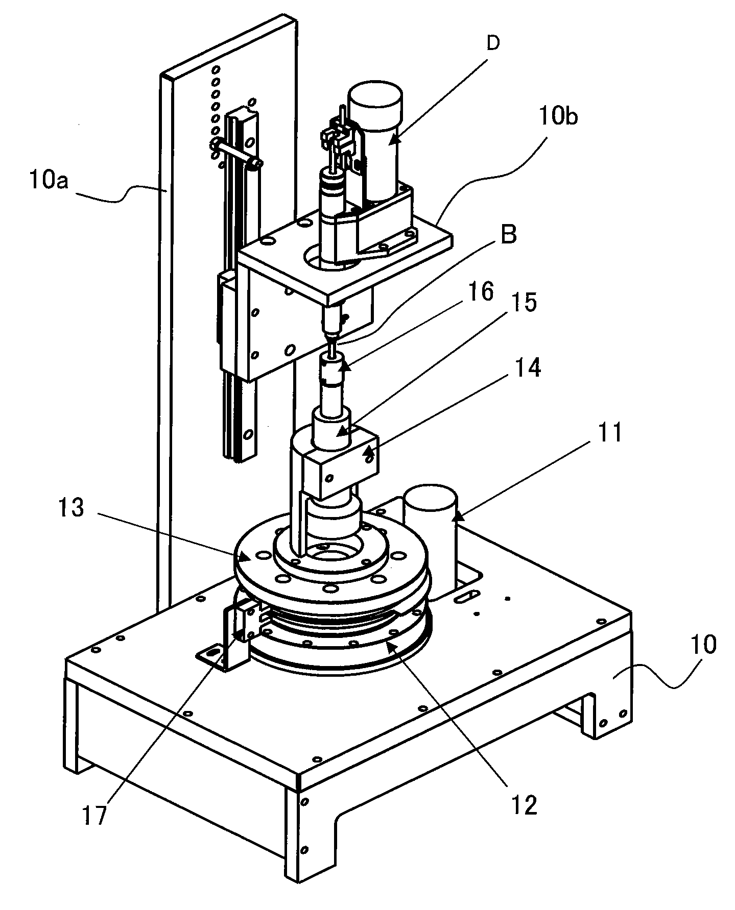
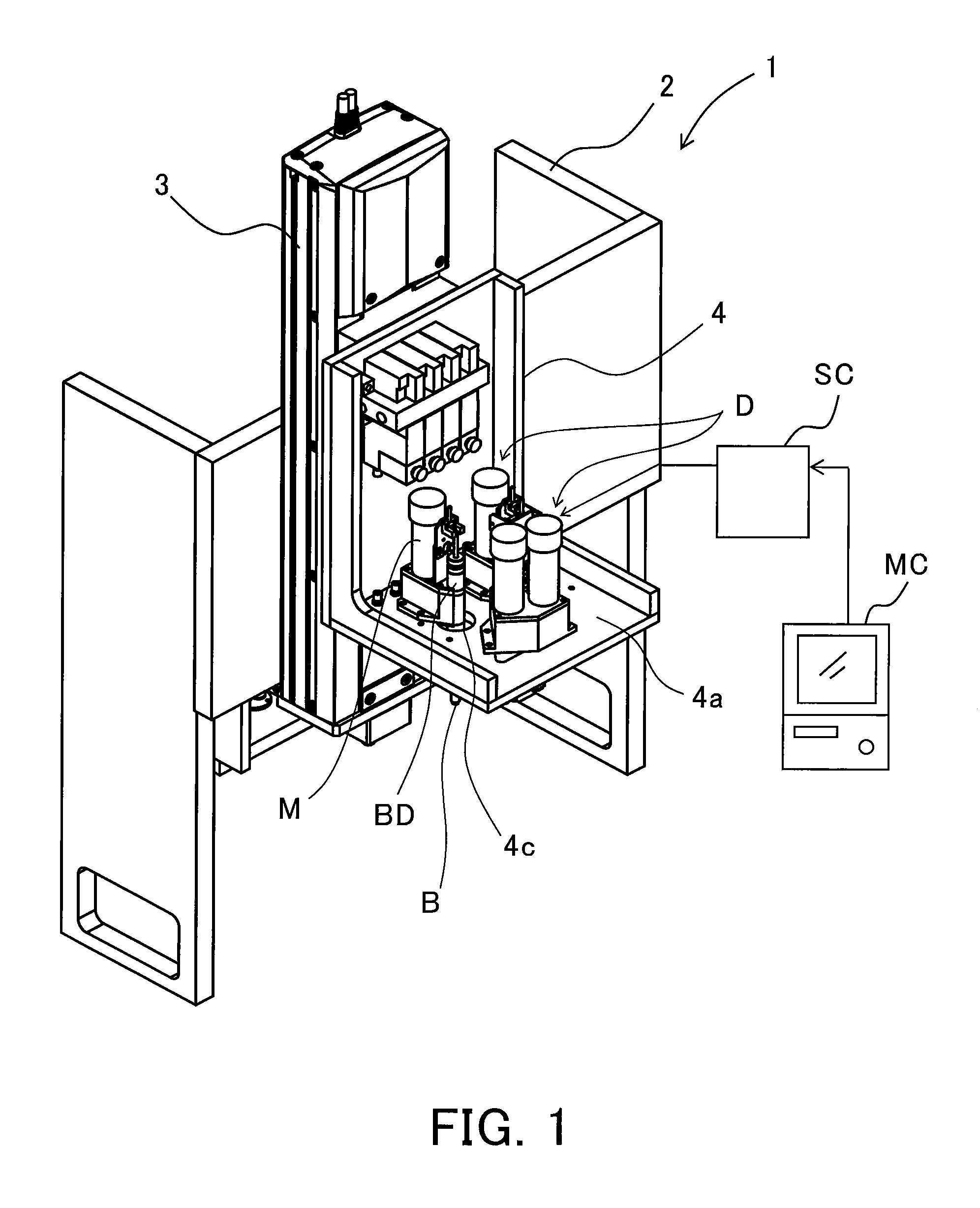
[0048]FIG. 1 illustrates the schematic configuration of a screw tightening system that is Embodiment 1 of the present invention. Reference numeral 1 denotes the entire screw tightening system of this embodiment. Reference numeral 2 denotes a main body of the screw tightening system 1 (hereinafter referred to as an apparatus main body). Reference numeral 3 denotes a lifting mechanism attached to the apparatus main body 2, the lifting mechanism moving a support table 4 up and down.

[0049]Plural (four in FIG. 1) screw tightening drivers (screw tightening apparatuses) D are attached on a horizontal plate 4a of the support table 4. Each of these screw tightening drivers D rotates a screw tightening bit B extending downward from the horizontal plate 4a through a through-hole 4c formed in the horizontal plate 4a. These screw tightening drivers D perform screw tightening operations with respect to a workpiece (an object for screw tightening) (not shown) which is disposed beneath the horizont...

embodiment 2

[0135]FIG. 8 shows a control procedure and operation timings of the screw tightening operations by a screw tightening system that is Embodiment 2 of the present invention. This embodiment shows an example of the case in which five screws are tightened with respect to a workpiece such as the clamp plate 25 or the like by the first to fifth drivers D1 to D5 (hereinafter called the drivers 1 to 5) among all the drivers D1 to D6 described in Embodiment 1. Constituent components in this embodiment identical to those in Embodiment 1 are denoted by the same reference numerals as those in Embodiment 1.

[0136]Embodiment 1 described the case in which the start timings of the seating operations and the torque increase operations of the respective drivers after the synchronization had differences. However, this embodiment will describe a case where the seating operations and the torque increase operations of all the drivers after synchronization are simultaneously started.

[0137]In FIG. 8, (a) to...

embodiment 3

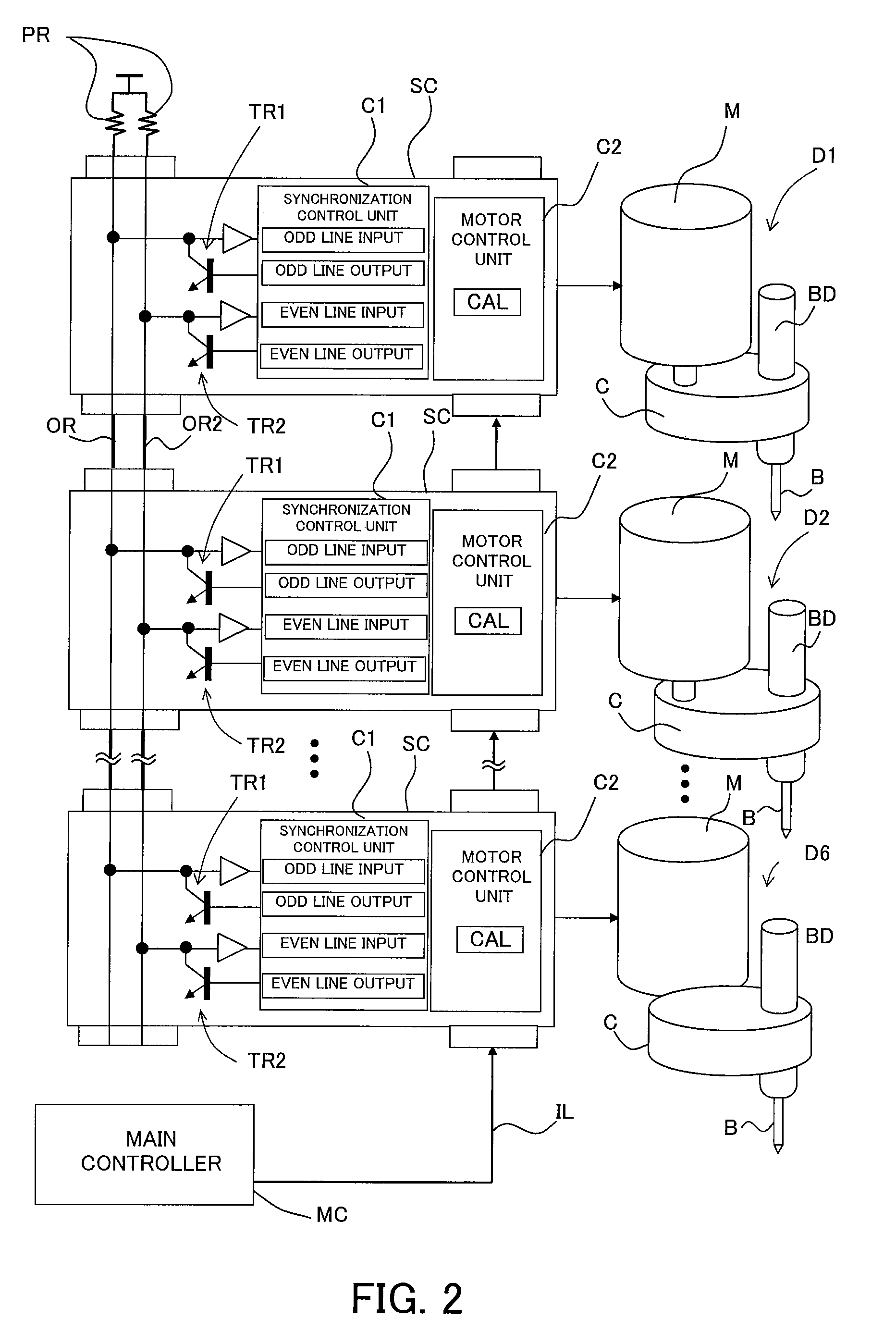
[0171]Embodiments 1 and 2 described the case where the synchronization control for the screw tightening drivers is performed by using the odd and even wired OR lines. However, the same synchronization control can be applied to a motor-driven apparatus other than the screw tightening drivers.

[0172]FIG. 9 illustrates a synchronization control system for performing position control of an object (a robot arm, a positioning table or the like) P in directions of four axes (X-, Y-, Z-, and θ-axes) which is Embodiment 3 of the present invention. Constituent components in this embodiment shown in FIG. 9 identical to those in Embodiment 1 are denoted by the same reference numerals as those in Embodiment 1. In this embodiment, synchronization control of motors MX, MY, MZ, and MO for drive in the directions of the X, Y, Z, and θ-axes in place of the screw tightening drivers in Embodiment 1 is performed.

[0173]FIG. 10 shows a control procedure and operation timings of this embodiment. This embodi...


PUM


Abstract

The screw tightening apparatus includes a motor, an output shaft to which a bit for screw tightening is connected so as to be rotatable integrally with the output shaft and which is axially movable, the output shaft being driven to be rotated by the motor, a spring whose one end contacts a member constituting a main body of the screw tightening apparatus, and a spring receiving member which the other end of the spring contacts and transmits a biasing force of the spring to the output shaft. The screw tightening apparatus further includes a conductive member which contacts the output shaft and the spring receiving member. This configuration enables static electricity generated on the bit to certainly flow into the main body of the apparatus (ground) via the output shaft, the conductive member, the spring receiving member, and the spring.

Description

[0001]This application is a continuation based on International Patent Application No. PCT / JP2006 / 0303913, filed on Mar. 1, 2006, which is hereby incorporated by reference herein in its entirety as if fully set forth herein.BACKGROUND OF THE INVENTION[0002]The present invention relates to a screw tightening apparatus that tightens a screw by motor driving.[0003]Screw tightening apparatuses include one in which a motor serving as a driving source and a bit engaging with a recess of a screw are offset in their radial direction (for example, refer to Japanese Patent Laid-Open No. 2003-25164). In many cases, such a so-called offset-type screw tightening apparatus is used in, for example, a case in which a plurality of screw tightening apparatuses are disposed so as to be adjacent to one another, to collectively performing the tightening of a plurality of screws disposed with a pitch narrower than a pitch between the motors.[0004]Further, in such an offset-type screw tightening apparatus...

Claims


Application Information

Patent Timeline
Patent Type & Authority Applications(United States)
IPC IPC(8): B23P19/06
CPCB23P19/066G01L5/24B23P19/00B23P19/06
Inventor KUBOYAMA, MAKOTO
Owner FUJITSU LTD
Why Eureka
Try Eureka