Radiant shield

Inactive Publication Date: 2008-12-25
DESPATCH INDS
View PDF24 Cites 244 Cited by
  • Summary
  • Abstract
  • Description
  • Claims
  • Application Information

AI Technical Summary

Benefits of technology

[0006]In yet another embodiment in accordance with the invention, a radiant shield and thermocouple combination usable in a continuous infrared furnace includes a mounting surface for attaching a radiant shield to a furnace wall and a radiant shield for obscuring a thermocouple from a radiant heat source. In this embodiment, the obscured radiant he

Problems solved by technology

The high volume fabrication and treatment of heat processed or

Method used


Image

  • Radiant shield
  • Radiant shield
  • Radiant shield

Examples


Embodiment Construction

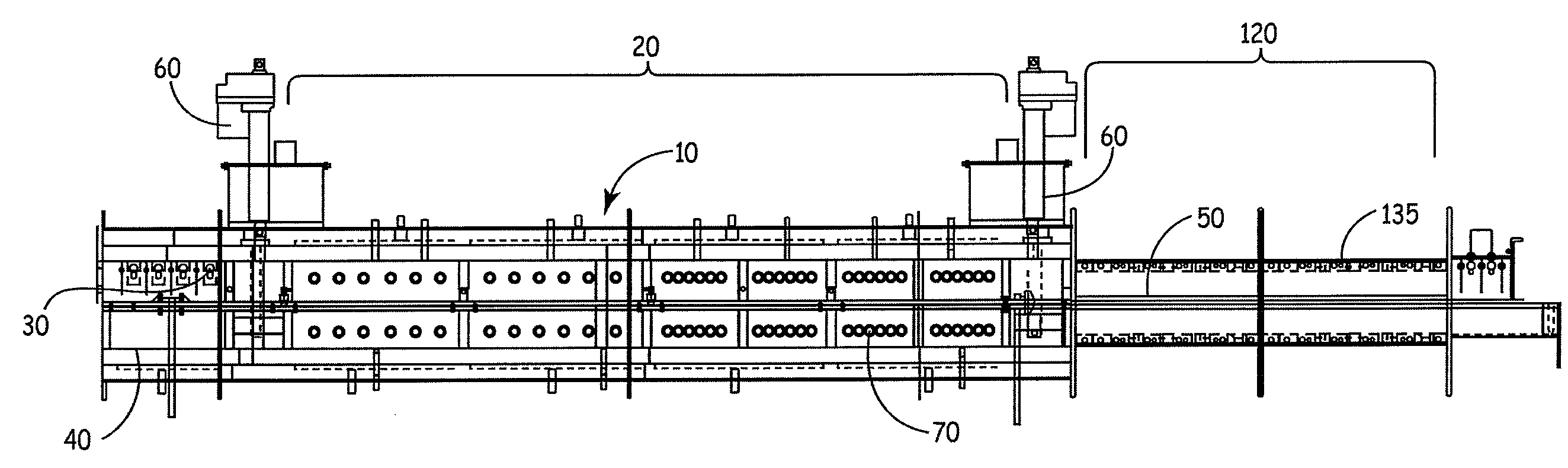
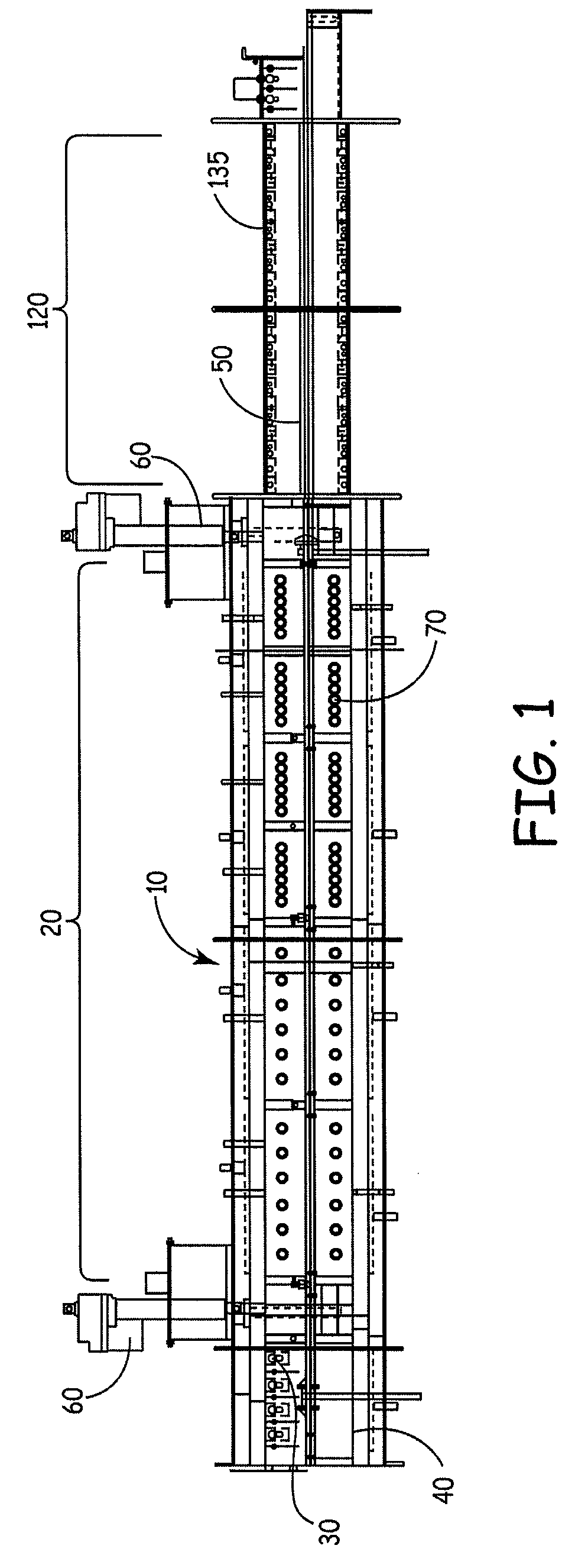
[0018]Turning now to the figures, FIG. 1 is a side view of an embodiment of a furnace in accordance with the invention. The furnace 10 has a heat transfer zone generally indicated at 20 for heating a material to be treated (not shown). The heat transfer zone 20 has an upper portion 30 and a lower portion 40. A conveyor 50 transports material to be treated through heat transfer zone 20 along a direction of travel. The conveyor 50 may be, for example, a conveyor belt, a walking beam, or other conveyor known in the art. An optional jack 60 allows movement of the lower portion 40 of the heat transfer zone 20 to allow access to the interior of the heat transfer zone 20 and to components therein. A jack 60, as used in this application, means a device for raising and lowering objects by means of force applied with a lever, screw, hydraulic press, or other means known in the art. The heat transfer zone 20 may also include one or more infrared lamps 70. These infrared lamps may be, for examp...


PUM


Abstract

A radiant shield and a furnace employing a radiant shield for controlled heating and treatment of material using infrared radiation. The furnace is capable of improved temperature control where material treated by the furnace may interfere with the quality of a measured temperature signal and temperature control based on that signal.

Description

FIELD OF THE INVENTION[0001]The invention is directed to a radiation shield for obscuring undesirable radiant heat sources from a temperature measuring device, and to techniques for improving performance, of temperature measuring devices in difficult environments.BACKGROUND OF THE INVENTION[0002]Infrared furnaces and ovens are widely used for in a variety of industries. Materials that may be treated in an infrared furnace may include painted or coated materials that require specific curing conditions, components that require heat melt solder (i.e. ball grid arrays), pre-heating metals, circuit boards, silicon wafers treated through zone-melt processes, materials for use in photovoltaic cells requiring conductive paste to be fused thereto, and any other material that one can conceive of that is can benefit from controlled infrared radiation.[0003]Control of the temperature within an infrared furnace may be important the quality and consistency of the products treated in such a furnac...

Claims


Application Information

Patent Timeline
IPC IPC(8): F27D11/00F26B3/30G01K1/12G01K7/02
CPCF26B3/30F27B9/36F27B9/40F27B17/0025F27D19/00F27D21/0014F27D99/00G01K1/12G01K7/02H01L21/67115
Inventor GRAHAM, ROBERT G.
Owner DESPATCH INDS
Why Eureka
Try Eureka