Method for Operating an Electronically Commutated Motor, and Motor for Carrying Out a Method Such as This

Active Publication Date: 2008-12-25
EBM PAPST ST GEORGEN & -
View PDF10 Cites 31 Cited by
  • Summary
  • Abstract
  • Description
  • Claims
  • Application Information

AI Technical Summary

Benefits of technology

[0014]The energy converted into heat is also “lost” and can no longer b

Problems solved by technology

Very high voltages can be caused as a result.
In terms of material costs, capacitors of this kind represent an economical solution to the aforementioned problem, but relatively large capacitors—usually so-called electrolyte capacitors—are required; their service life is limited, a

Method used


Image

  • Method for Operating an Electronically Commutated Motor, and Motor for Carrying Out a Method Such as This
  • Method for Operating an Electronically Commutated Motor, and Motor for Carrying Out a Method Such as This
  • Method for Operating an Electronically Commutated Motor, and Motor for Carrying Out a Method Such as This

Examples


Embodiment Construction

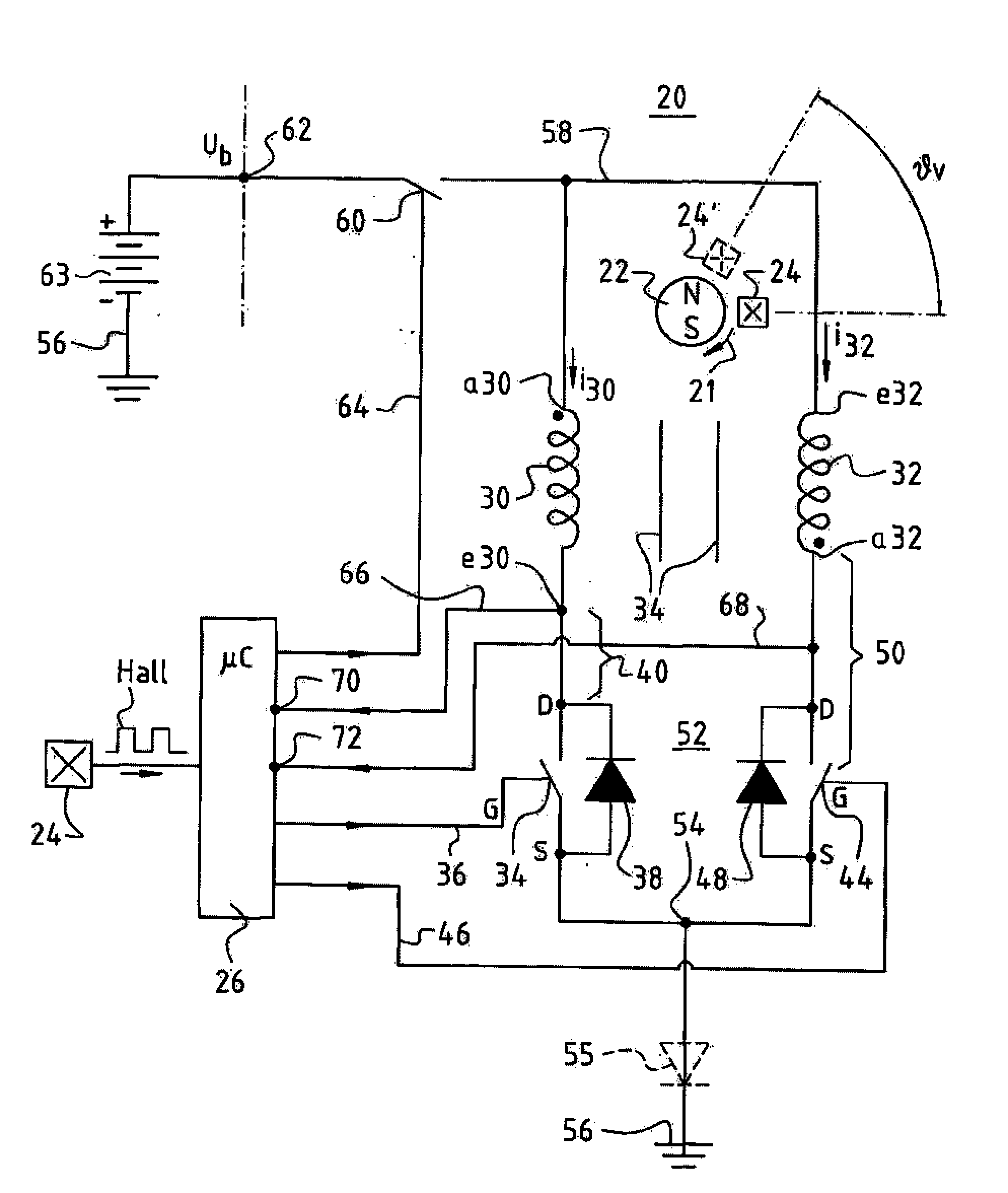
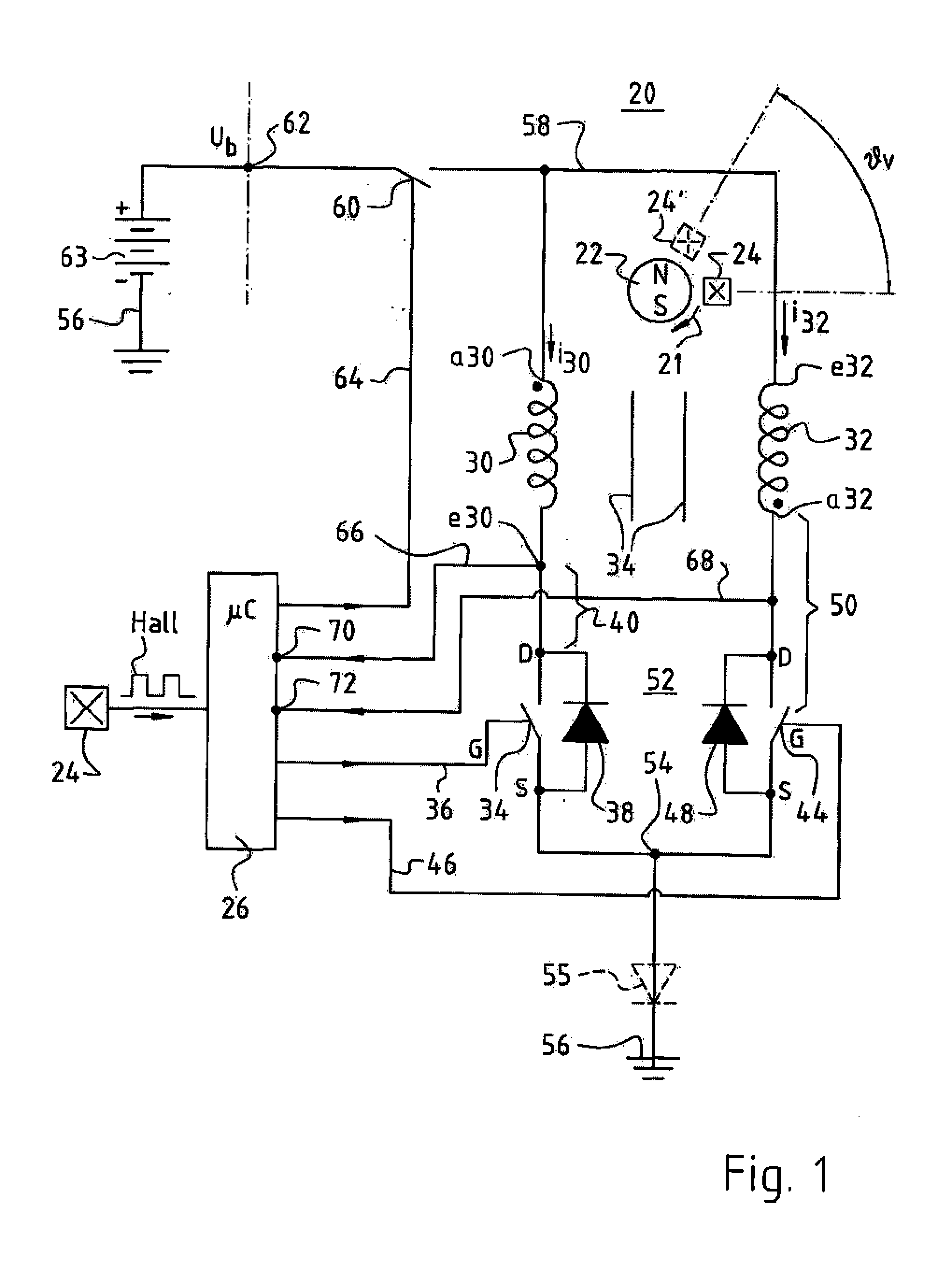
[0036]FIG. 1 is a schematic depiction of a motor 20 according to a preferred embodiment of the invention. It has a permanent-magnet rotor 22 (indicated only schematically), whose rotation direction is designated 21 in order to depict graphically the offset of a Hall sensor 24 oppositely to the rotation direction. Rotor 22 is depicted as having two poles, but it can also have four, six, etc. poles; and it can be, for example, an internal rotor, an external rotor, or the rotor of a motor having a flat or conical air gap.

[0037]This rotor 22 controls Hall sensor 24, which is also depicted to the left in FIG. 1 and generates, in operation, a “Hall” signal that is depicted schematically in FIG. 1 and is supplied to a microcontroller μC 26 that is associated with motor 20 and is usually built into it. The provision of current to μC 26 at a regulated voltage of, for example, 5 V is not depicted, since it is known to one skilled in the art. μCs of this kind are used in very large numbers in ...


PUM


Abstract

An electronically commutated motor (ECM 20) has terminals (56, 62) for connection to a DC power source (63). It has a permanent-magnet rotor (22), also a first and a second series circuit (40, 50) in each of which a stator winding strand (30, 32) is connected in series with a controllable semiconductor switch (34, 44), which two series circuits are connected in parallel to form a parallel circuit (52). In addition to the strand-connected switches (34, 44) typically found in an ECM, in a supply lead to said parallel circuit (52), a third controllable semiconductor switch (60) controls energy supply from the DC power source (63). In order to increase motor efficiency and minimize the size of any motor capacitor required, special switching steps are performed so that electromagnetic energy, remaining in the winding(s) after shutoff of power application, is converted into motor torque, instead of being dissipated as heat.

Description

CROSS-REFERENCE[0001]This application is a section 371 of PCT / EP07 / 04845, filed 1 Jun. 2007, published 13 Dec. 2007 as WO 2007-140927-A.FIELD OF THE INVENTION[0002]The present invention relates to a method for operating an electronically commutated motor, and to a motor for carrying out such a method.BACKGROUND[0003]There are various designs for electronically commutated motors. One known classification system is based on the number of current pulses supplied to the stator of such a motor for each rotor revolution of 360° el. A distinction can therefore be made between one-pulse motors, in which only a single driving current pulse is supplied during one rotor revolution of 360° el.; two-pulse motors, in which two stator current pulses, which are usually spaced apart in time from one another, are supplied during one rotor revolution of 360° el.; and also three-pulse, six-pulse, etc. motors.[0004]Such motors are further classified according to their number of stator winding strands, i...

Claims


Application Information

Patent Timeline
IPC IPC(8): H02P6/14
CPCH02P6/15H02P6/34
Inventor LOFFLER, JENSKUNER, ARNOLD
Owner EBM PAPST ST GEORGEN & -
Why Eureka
Try Eureka