
Heat dissipation structure for electronic devices

a technology of electronic devices and heat dissipation structures, applied in the direction of insulated conductors, power cables, cables, etc., can solve the problems of affecting the stability of the system, operating electronic elements inevitably generate heat, and the miniaturized or vehicular computer usually carries many complicated electronic elements in a very limited space, so as to simplify the structure of heat dissipation devices, the effect of low space efficiency

Inactive Publication Date: 2008-12-25
SHUTTLE
View PDF12 Cites 7 Cited by
  • Summary
  • Abstract
  • Description
  • Claims
  • Application Information

AI Technical Summary

Benefits of technology

[0005]The primary objective of the present invention is simplify the structure of heat dissipation devices to meet the dimensions of a miniature or vehicular computer and to solve the conventional problem that too many heat dissipation devices result in low space efficiency and inferior heat dissipation.
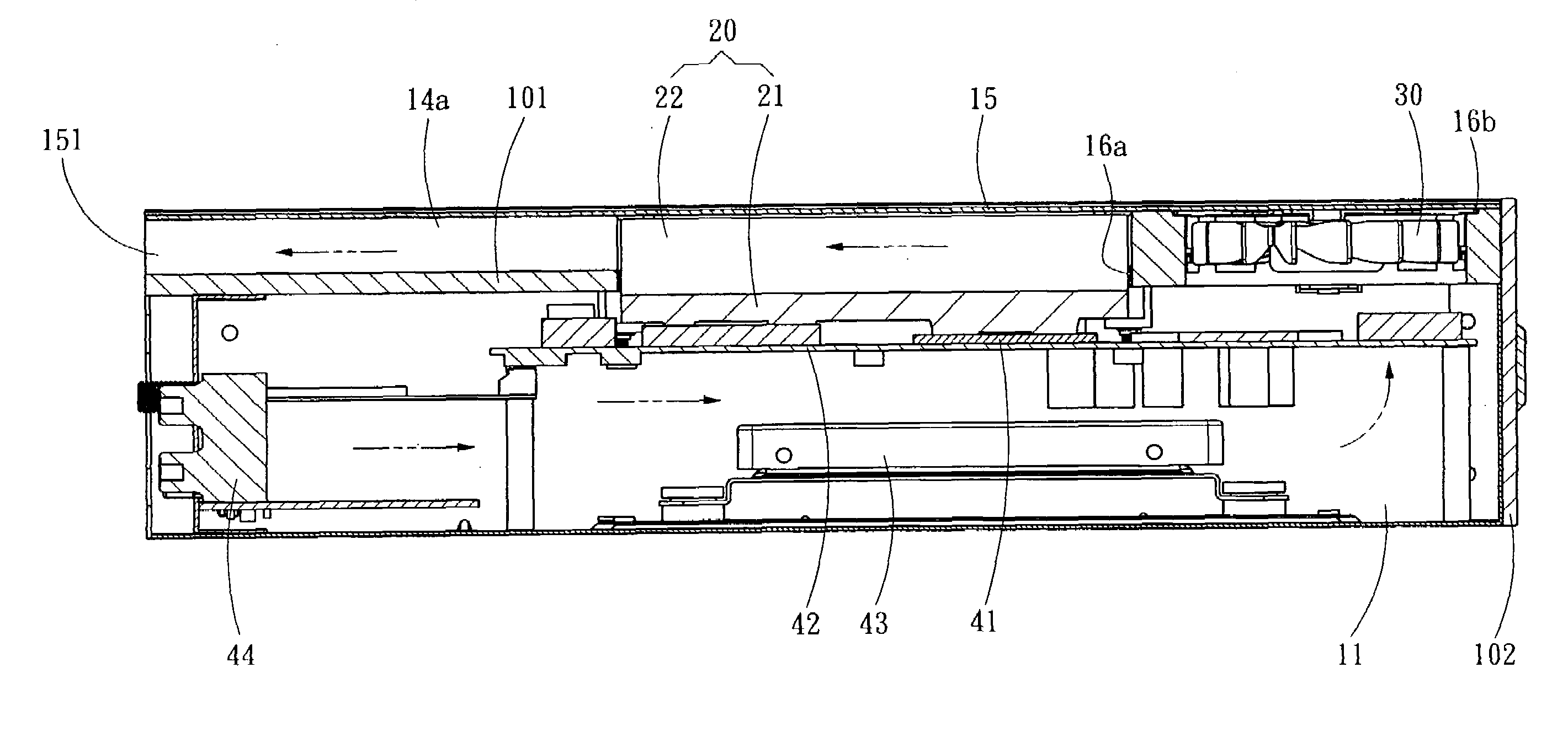
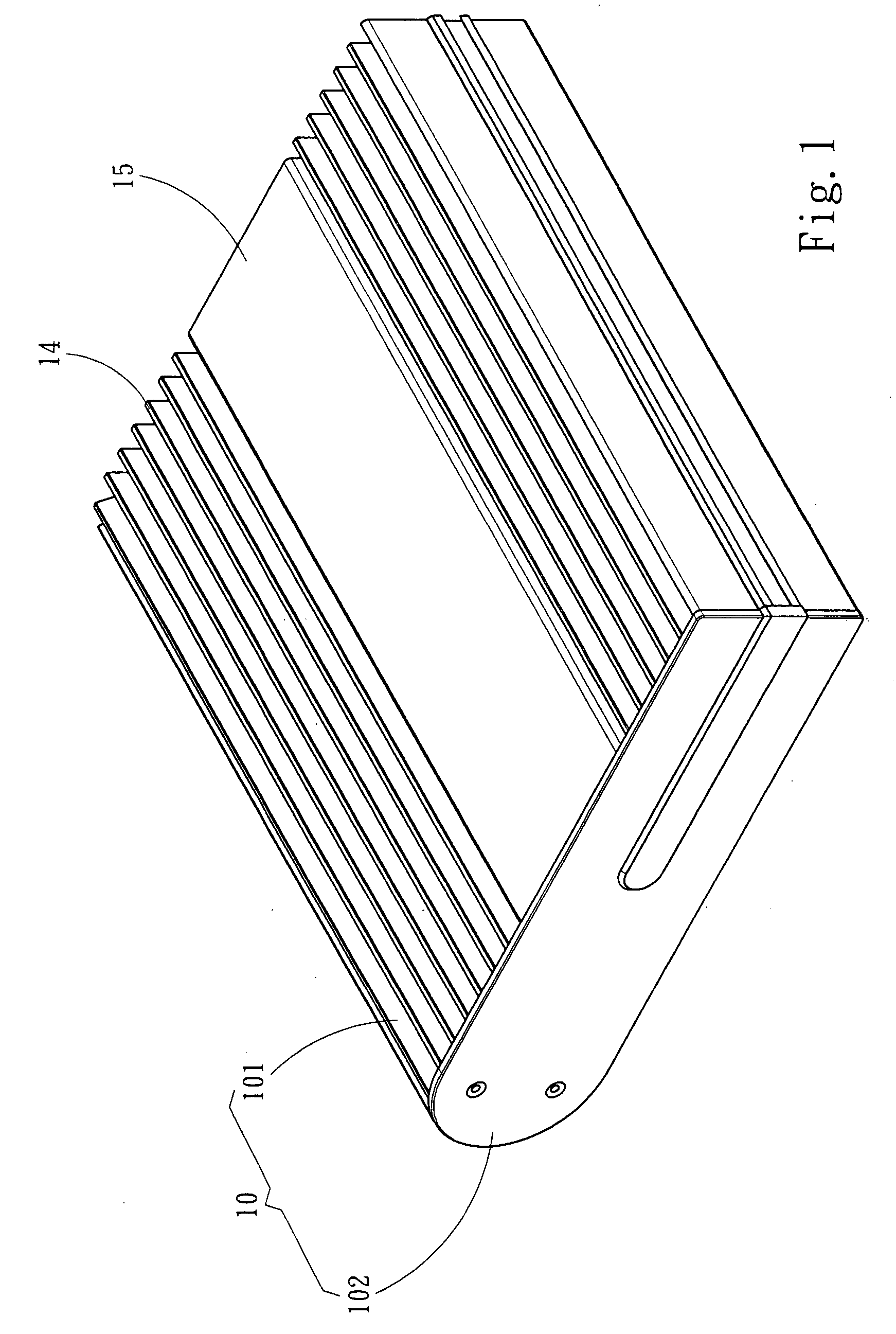
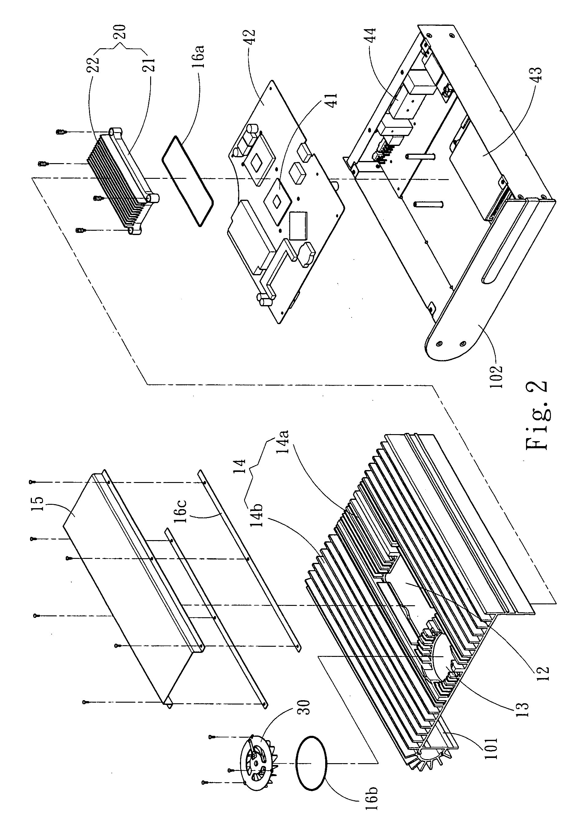
[0006]To achieve the abovementioned objective, the present invention proposes a heat dissipation structure for electronic devices, which comprises a housing, a heat conductor and an electric fan. The housing further comprises an upper casing and a lower casing, which are joined together to form an accommodation space. The accommodation space accommodates at least one heat-generating element. The heat conductor is also accommodated in the accommodation space and further comprises a heat conduction block contacting the heat-generating element and a plurality of first heat dissipation fins. The housing is made of a heat conduction material and has a plurality of second heat dissipation fins parallel to the first heat dissipation fins. The upper casing has an opening corresponding to the heat conductor, and the first heat dissipation fins of the heat conductor extend through the opening and emerge from the housing. Thus, the heat generated by the heat-generating element can be dissipated to the exterior of the electronic device via the conduction of the heat conductor. The upper casing also has an air suction opening corresponding to the electric fan. The electric fan drains out the hot air inside the accommodation space via the air suction opening and drives the air to flow through the first heat dissipation fins; thus, heat dissipation efficiency is promoted. A cover is arranged over the upper casing and simultaneously spans the opening and the electric fan. The cover cooperates with the upper casing to define an air current tunnel and form an air current outlet. An air current is driven by the electric fan to unidirectionally flow along the air current tunnel and through the heat conductor and then goes out from the air current outlet.

Problems solved by technology

Especially, a miniature or vehicular computer usually carries many complicated electronic elements in a very limited space.
Operating electronic elements inevitably generate heat, which influences the stability of the system.
However, for an electronic apparatus having many electronic devices elaborately arranged, too many heat dissipation elements is unfavorable to miniaturization and compactness.
Besides, a plurality of cooling fans operating at high speed generates considerable noise and vibration or even causes internal air turbulence, which may contrarily impair draining heat.
As the two conventional technologies mentioned above do not adopt any cooling fan, they can noiselessly lower the interior temperature of a computer.
However, the pure passive cooling technologies are limited by the heat conductivity of heat conduction materials.
Hence, they cannot be extensively applied to all electronic devices.

Method used


Image

  • Heat dissipation structure for electronic devices
  • Heat dissipation structure for electronic devices
  • Heat dissipation structure for electronic devices

Examples


Embodiment Construction

[0010]Below, the technical contents of the present invention are described in detail in cooperation with the drawings.

[0011]Refer to FIG. 1, FIG. 2 and FIG. 3 respectively a perspective view, an exploded view and a sectional view schematically showing one preferred embodiment of the present invention. The present invention is a heat dissipation structure for electronic devices, which comprises: a housing 10, a heat conductor 20 and an electric fan 30. The housing 10 further comprises an upper casing 101 and a lower casing 102, which are joined together to form an accommodation space 11. The accommodation space 11 accommodates at least one heat-generating element, such as CPU 41, a display card, a power supply, etc. (in this embodiment, CPU 41 is used to exemplify the heat-generating element), and other electronic devices, such as a main board 42, a hard drive 43, an I / O interface 44, etc. The heat conductor 20 is also accommodated in the accommodation space 11 and further comprises ...


PUM


Abstract

The present invention discloses a heat-dissipation structure for electronic devices, which comprises: a housing having an accommodation space accommodating at least one heat-generating element; a heat conductor arranged in the accommodation space and contacting the heat-generating element; and an electric fan arranged outside the housing. The housing has an opening corresponding to the heat conductor, and the heat conductor extends through the opening and projects from the housing. The electric fan drives an air current to flow through the part of the heat conductor extending through the opening to promote heat-dissipation efficiency.

Description

FIELD OF THE INVENTION[0001]The present invention relates to a heat dissipation structure, particularly to a heat dissipation structure, wherein the heat generated by electronic devices is directly conducted to the exterior by a heat conduction element.BACKGROUND OF THE INVENTION[0002]With the persistently progressive electronic technology, computer science is also widely applied in various fields. The current computer has greatly advanced in function and speed and has been able to process massive and complicated data. In addition to having superior performance, the current computer is also getting slimmer and compacter. Especially, a miniature or vehicular computer usually carries many complicated electronic elements in a very limited space. Operating electronic elements inevitably generate heat, which influences the stability of the system. Thus, heat dissipation technologies are developed to solve such a problem.[0003]Heat dissipation technologies include active cooling technolog...

Claims


Application Information

Patent Timeline
Patent Type & Authority Applications(United States)
IPC IPC(8): H05K7/20
CPCG06F1/20H05K7/20409
Inventor LIU, CHIEN-HSIANGYEH, FUN-SONCHANG, BRIAN
Owner SHUTTLE
Learn More