Transmit power control module and associated method for transmit power configuration

a technology of transmit power and control module, which is applied in power management, transmission path division, wireless communication, etc., can solve the problems of large increase in injected noise in nearby lines, instability of the network, etc., and achieves the optimization of the configuration of the boost, avoid abuse or configuration errors, and avoid excessive noise injection.

Inactive Publication Date: 2008-12-25
ALCATEL LUCENT SAS
View PDF4 Cites 9 Cited by
  • Summary
  • Abstract
  • Description
  • Claims
  • Application Information

AI Technical Summary

Benefits of technology

[0033]The method first establishes the basic output power or transmit power of the transmitter based on a first set of parameters. Optionally the transmitter takes line attenuation into account when determining this first contribution. This way, the transmitter can generate a signal which is of a power level that is acceptable for the receiver and which avoids excessive noise injection on nearby communication lines. The method then involves generating a boost or second contribution to the transmit power which alters the output power in such a way that the signal beco

Problems solved by technology

Small variations in the parameter value setting for transmit power control may lead to large cons

Method used


Image

  • Transmit power control module and associated method for transmit power configuration
  • Transmit power control module and associated method for transmit power configuration
  • Transmit power control module and associated method for transmit power configuration

Examples


Embodiment Construction

)

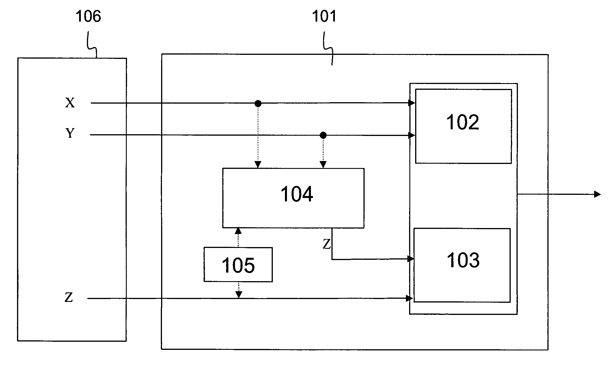
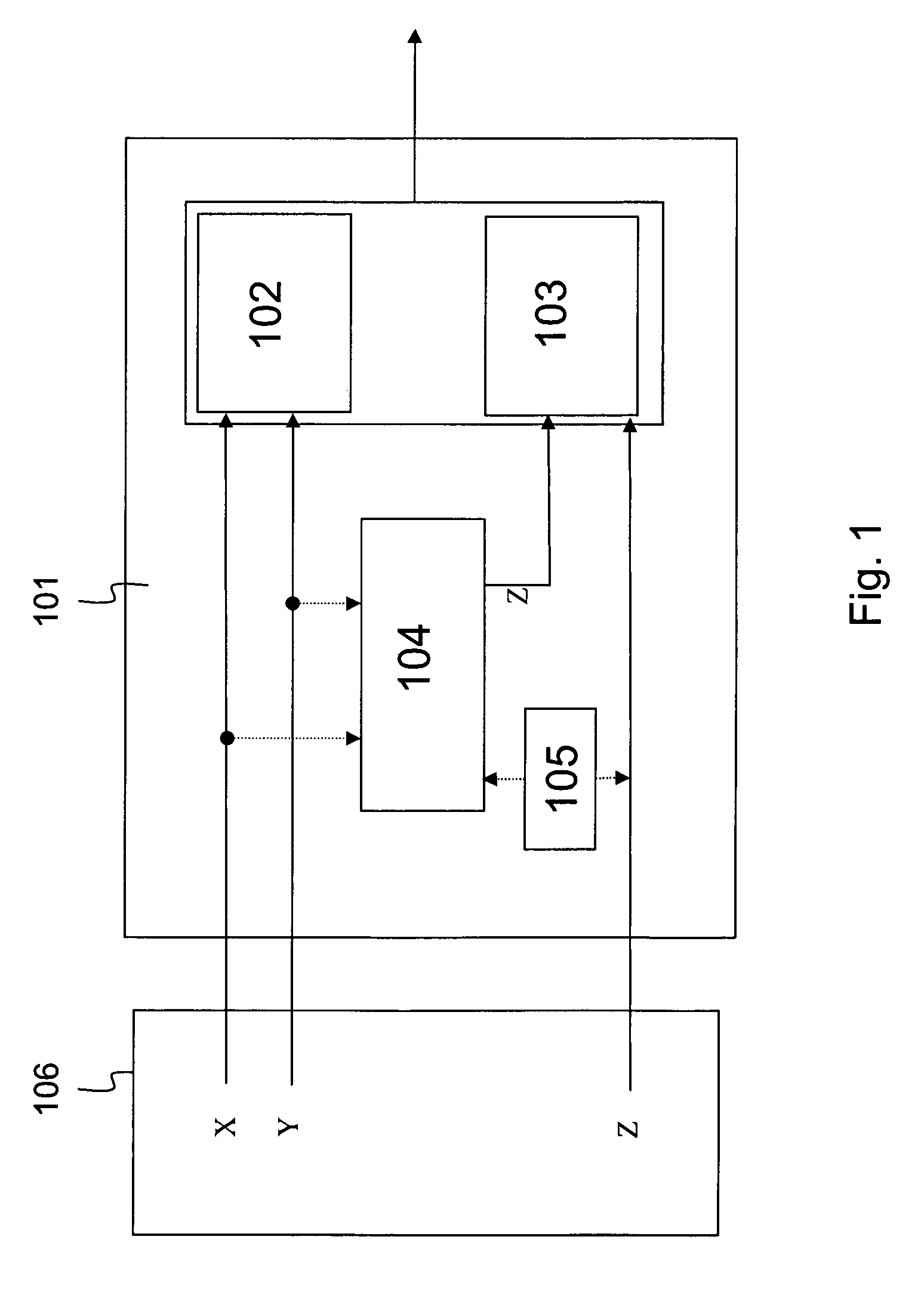
[0036]FIG. 1 shows a transmit power control module 101 and a configuration interface 106 connected thereto. In this particular embodiment, the transmit power control module 101 is incorporated in a VDSL modem connected to a DSLAM at the central office and the configuration interface 106 is part of the operators network management platform. In a typical setup, the operator will determine the values for parameters X and Y for each user or group of users according to the VDSL standard specification and configure these values via the configuration interface 106. When a user turns his VDSL modem on, the parameters X and Y are transmitted to the modem. The VDSL modem will use the values of X and Y for calculating the transmit power for upstream transmission.

[0037]Calculation element 102 will receive the values for X and Y and determine a first contribution to the output power according to the formula PSD1(f)=−X−Y·√{square root over (f)}. The calculation element 102 can use an attenuation...


PUM


Abstract

A module (101) for controlling the transmit power of a signal transmitter. The output power is determined from a first contribution based on a first set of parameters configured by an operator and a second contribution based on a second set of parameters. The module (101) is able to configure the second set of parameters based on the first set of parameters.

Description

FIELD OF THE INVENTION[0001]The present invention generally relates to the control of transmit power and more particular to configuring control parameters for the Power Spectral Density (PSD) in a digital communications system, such as for instance upstream or downstream communication on a DSL line.BACKGROUND OF THE INVENTION[0002]An important problem in digital communications is cross-talk between multiple communication lines. Cross-talk is the effect wherein the information transported over a first communication line affects a second, nearby communication line as a result of electromagnetic radiation. The noise induced in the second line may affect the information transported on the second line. A single transmission line in a larger bundle will typically experience crosstalk from all other lines in that bundle. The induced crosstalk will increase with the transmit power or PSD.[0003]The length of the communication line plays an important role in the influence of cross-talk on tha...

Claims


Application Information

Patent Timeline
IPC IPC(8): H04L27/00
CPCH04L5/0007H04L5/0058H04M11/062H04W52/246H04M3/30H04L27/26
Inventor PASCAL, JEAN-MARC
Owner ALCATEL LUCENT SAS
Why Eureka
Try Eureka