Multiple path air mass flow sensor assembly

a sensor and air mass technology, applied in the direction of instruments, electric control, combustion air/fuel air treatment, etc., can solve the problems of difficult accurate flow measurement, large volume of air provided, and difficult to improve the many conflicting operational parameters of the last several decades, so as to improve the high-volume air flow, reduce flow resistance, and improve measurement accuracy

Inactive Publication Date: 2009-01-01
GM GLOBAL TECH OPERATIONS LLC
View PDF16 Cites 23 Cited by
  • Summary
  • Abstract
  • Description
  • Claims
  • Application Information

AI Technical Summary

Benefits of technology

[0010]The air mass flow sensor assembly according to the present invention exhibits improved measurement accuracy at low flow rates because the sensor is located in a duct smaller than those currently used with a comparable engine while providing reduced flow resistance and improved high volume air flow. Both parallel and non-parallel ducts defining parallel and non-parallel flow pathways as well as multiple, staged or sequenced bypass ducts and ducts having different areas or flow rates are also within the scope of this invention.
[0011]Thus it is an object of the present invention to provide an air mass flow sensor assembly having improved low flow rate measurement accuracy.
[0012]It is a further object of the present invention to provide an air mass flow sensor assembly having improved high flow rate capability.
[0013]It is a still further object of the present invention to provide an air mass flow sensor assembly having improved low flow rate measurement accuracy and high flow rate capacity.

Problems solved by technology

In fact, the great improvements in these often conflicting operational parameters of the last several decades would simply not have been possible without the use of these systems.
This can be a challenge because the often convoluted duct and varying air velocities may create complex flow patterns which render accurate flow measurement difficult.
This problem is especially acute at low flow rates which represent the most critical engine operating condition from the standpoints of emissions and fuel economy.
Although reducing the size of the intake duct would seem to be a solution to this problem, since the size of the intake duct is mandated by the air flow requirements of the engine at full load, reducing its size at the sensor location to improve measurement accuracy reduces the volume of air provided to the engine, increases flow resistance and will thus interfere with achieving maximum engine power output.
A larger intake duct, however, reduces the flow velocity and, as noted, renders air mass flow measurement more difficult, particularly under low flow conditions—precisely those conditions that are most critical to optimum engine operation.

Method used


Image

  • Multiple path air mass flow sensor assembly
  • Multiple path air mass flow sensor assembly
  • Multiple path air mass flow sensor assembly

Examples


Embodiment Construction

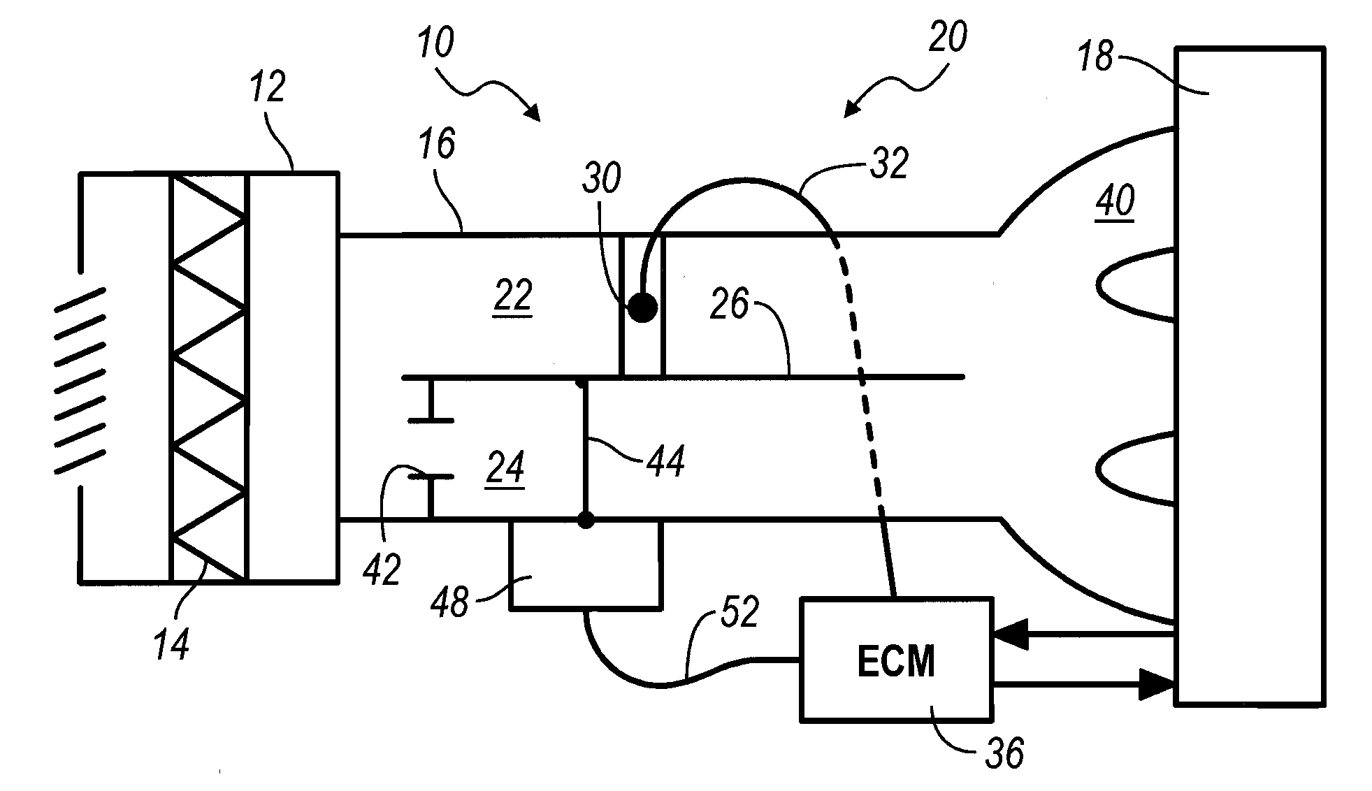
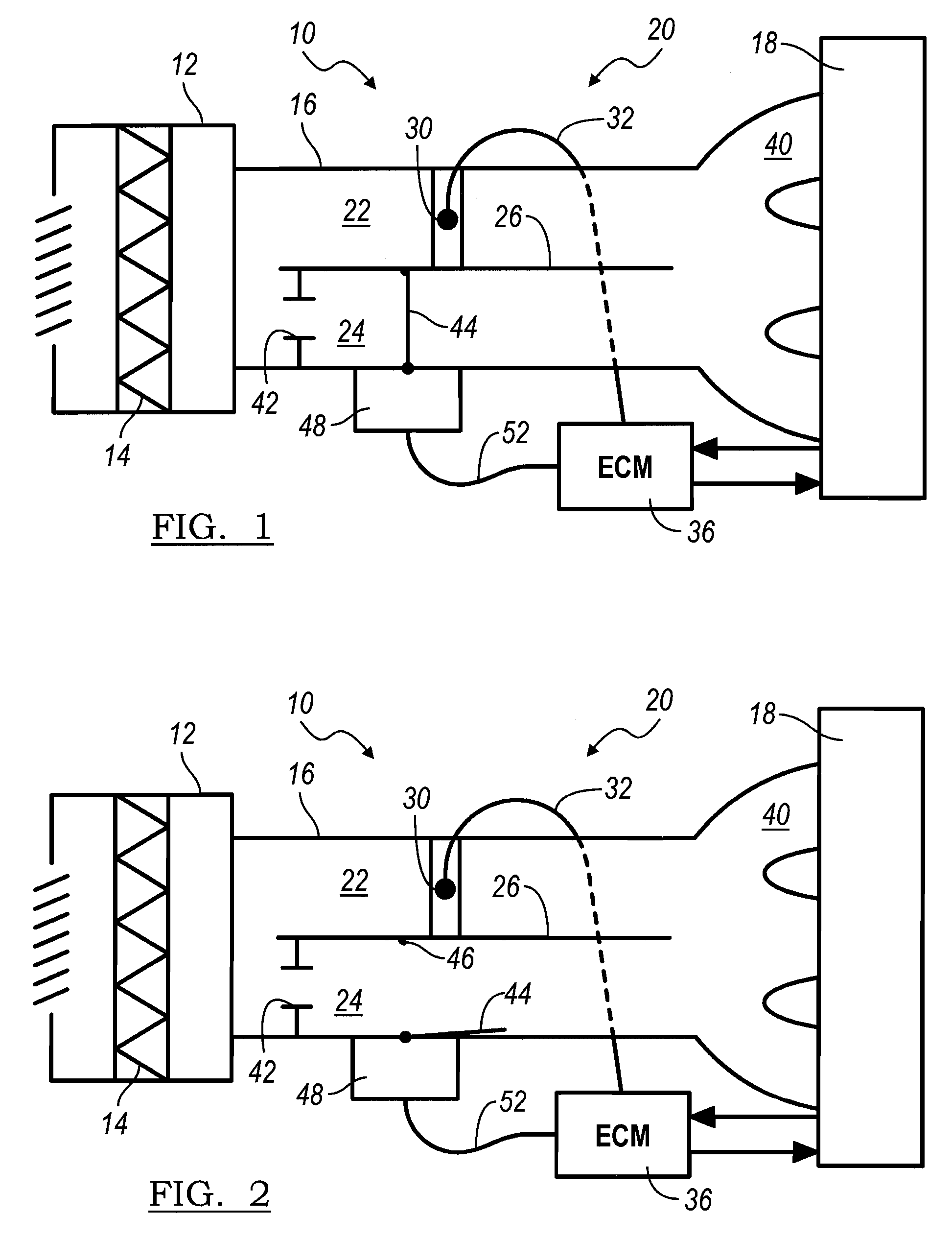
[0021]Referring now to FIG. 1, an inlet or intake duct assembly for an internal combustion engine is illustrated and designated by the reference number 10. The intake duct assembly 10 includes an air filter assembly 12 which draws in ambient air and includes an air filtration element 14. The air filter assembly 12 communicates with an air inlet or intake duct 16 which provides combustion air to an internal combustion engine 18. In a first embodiment of an air mass flow sensor assembly 20 according to the present invention, the air inlet or intake duct 16 is separated into a first, sensing duct 22 and a second, bypass duct 24 by a divider or partition 26. While illustrated as parallel, it should be understood that the first, sensing duct 22 and the second, bypass duct 24 may be separate, non-parallel and sinuous or convoluted, for example, to fit within available under-hood space or match and connect to air inlet and engine components.

[0022]Disposed within the first, sensing duct 22 ...


PUM


Abstract

A multiple path air mass flow sensor assembly includes an inlet duct which is divided into at least two separate ducts. A first duct has an air mass flow sensor disposed in conventional fashion therein. A second duct includes a damper or valve which may be selectively, partially or fully opened. At low air flow rates, the damper is closed forcing all air through the first duct. As engine speed increases and the air mass flow rate increases, the damper opens, either fully at a predetermined flow rate or proportionally over a predetermined flow rate range, to allow a larger volume of air through the inlet duct. The signal from the air mass flow sensor is adjusted by the engine controller to compensate for the (bypass) air flowing through the second duct.

Description

BACKGROUND OF THE INVENTION[0001]1. Field of the Invention[0002]The invention relates generally to air mass flow sensors and more particularly to a multiple path air mass flow sensor having improved measurement accuracy.[0003]2. Description of the Prior Art[0004]Modern internal combustion engines typically intended for use in passenger vehicles and trucks include extensive use of operational sensors and microprocessors to control engine operation, improve performance and fuel economy, and reduce emissions. In fact, the great improvements in these often conflicting operational parameters of the last several decades would simply not have been possible without the use of these systems.[0005]One of the most commonly used sensors with an internal combustion engine and electronic controller is an air mass flow sensor. Typically, an air mass flow sensor includes a resistance element which is located in an air intake duct, often immediately after the air filter and before the duct is subdiv...

Claims


Application Information

Patent Timeline
Patent Type & Authority Applications(United States)
IPC IPC(8): G01F1/00G01M99/00
CPCF02D41/18F02D2200/0402F02M35/10019F02M35/10157G01F7/00F02M35/10386F02M35/108G01F1/6842G01F5/00F02M35/10295
Inventor REDON, FABIEN G.
Owner GM GLOBAL TECH OPERATIONS LLC
Why Eureka
Try Eureka