System and process for water treatment

a water treatment system and high shear technology, applied in biological water/sewage treatment, separation processes, filtration separation, etc., can solve the problems of large amount of discarded water, and achieve the effect of reducing the overall cost, reducing the residence time, and increasing the water treatment process ra

Active Publication Date: 2009-01-01
HRD CORP
View PDF39 Cites 13 Cited by
  • Summary
  • Abstract
  • Description
  • Claims
  • Application Information

AI Technical Summary

Benefits of technology

[0010]A high shear system and a high shear process for enhancing water treatment are disclosed. The high shear system and process may reduce mass transfer limitations relative to conventional water treatment systems and processes, thereby increasing the water treatment rate and potentially permitting a reduction in contact time, an increased removal / neutralization of undesirable contaminants, and / or a reduction in treatment aid. The system and process employ an external high shear mechanical device to provide enhanced contact between reactants. In some embodiments, this enhanced contact results in accelerated chemical reactions between multiphase reactants. In an embodiment, the process comprises the use of an external pressurized high shear device to provide for water treatment without the need for large volume vessels in which the water spends high residence times.
[0014]Certain embodiments of an above-described method or system potentially provide for more optimal time, temperature and pressure conditions than are otherwise possible, and which potentially increase the rate of the water treatment process. Certain embodiments of the above-described methods or systems potentially provide overall cost reduction by operating with reduced residence times, providing increased product per unit of treatment aid consumed, and / or reduced capital and / or operating costs. These and other embodiments and potential advantages will be apparent in the following detailed description and drawings.

Problems solved by technology

Processes for the recovery of waste water from industrial operations present challenging environmental issues and the government regulates these processes.
For example, the waste water often comprises significant amounts of suspended solids, undesirable dissolved minerals, and noxious gases.

Method used


Image

  • System and process for water treatment
  • System and process for water treatment
  • System and process for water treatment

Examples


Embodiment Construction

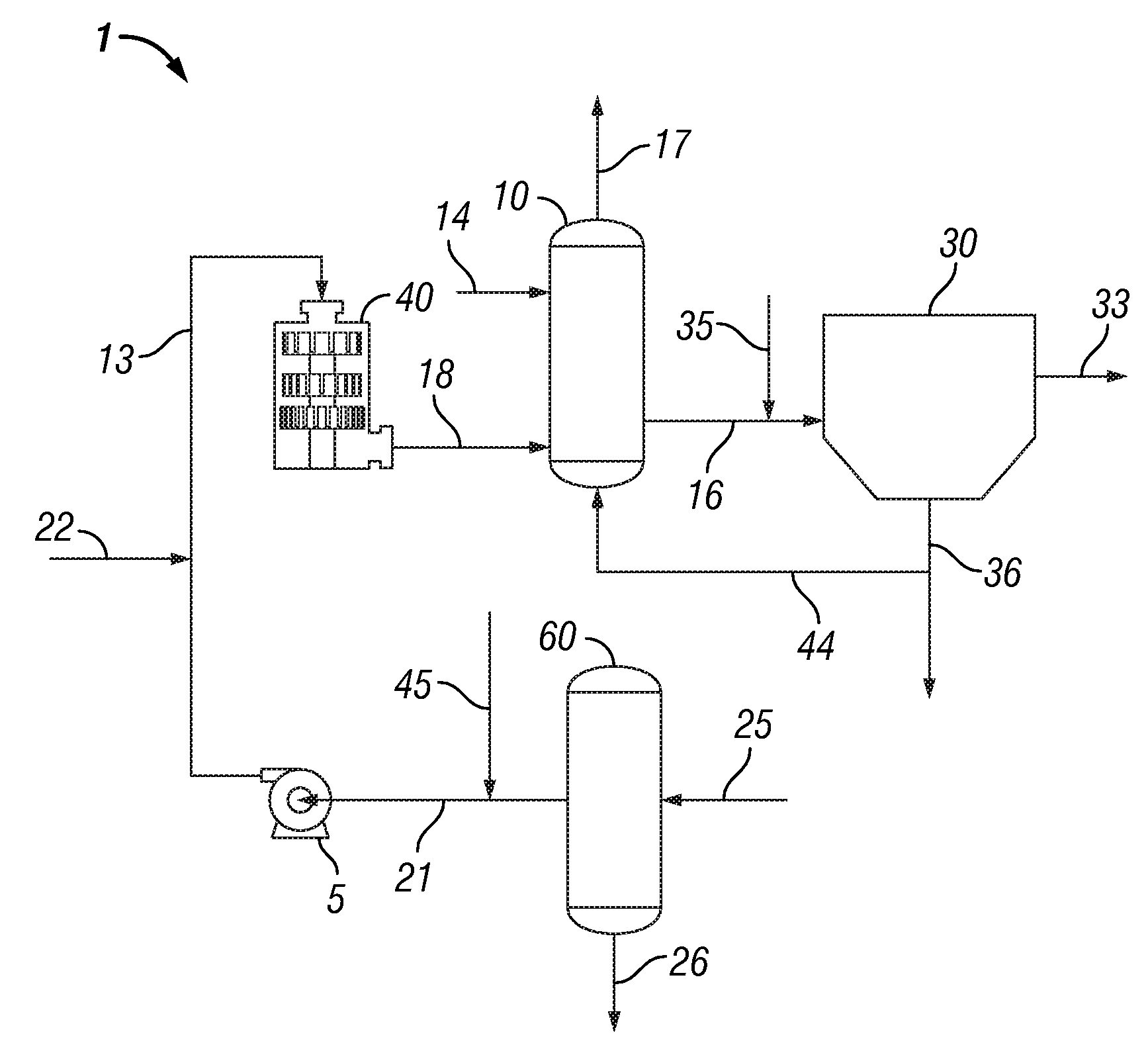
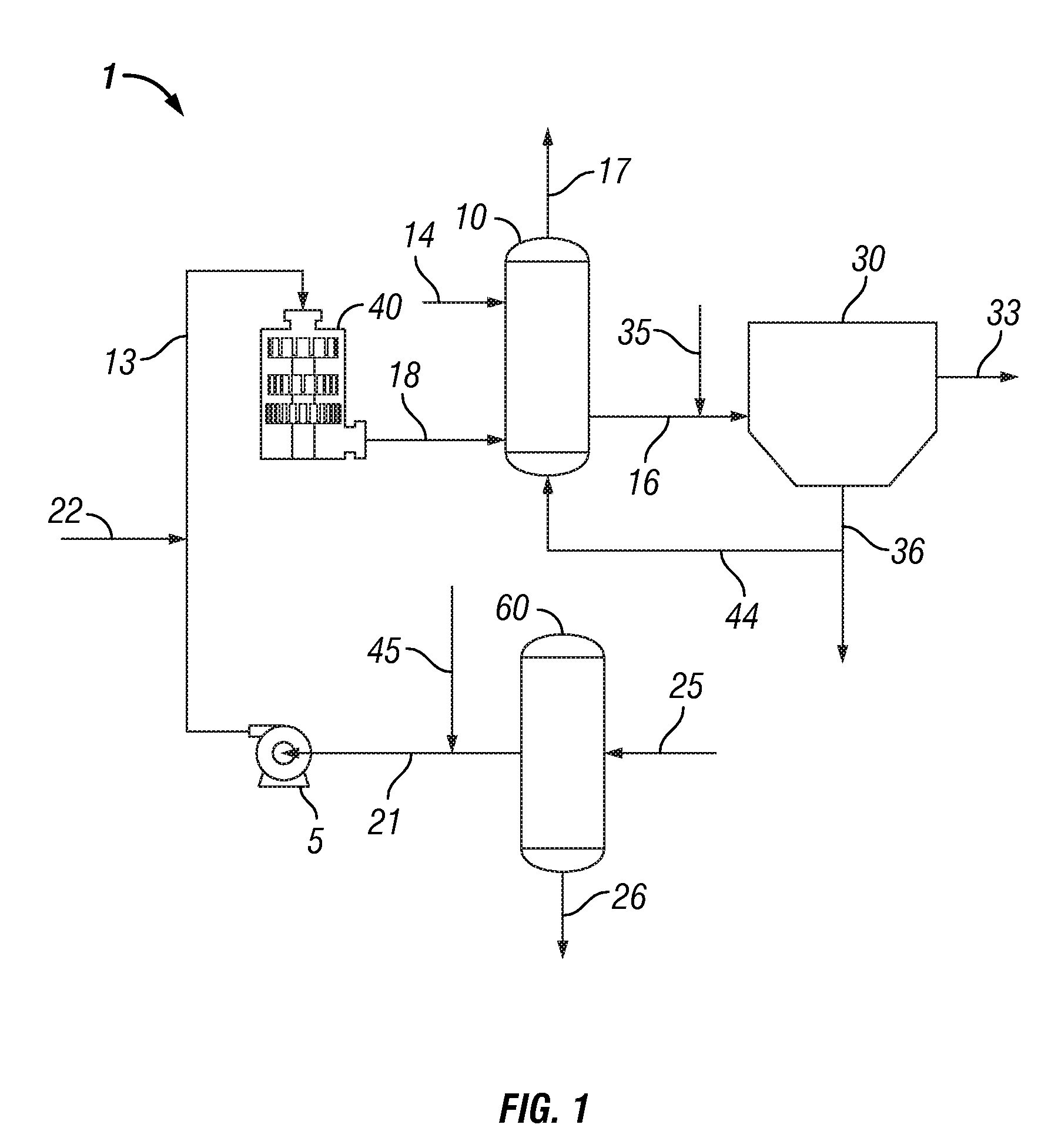
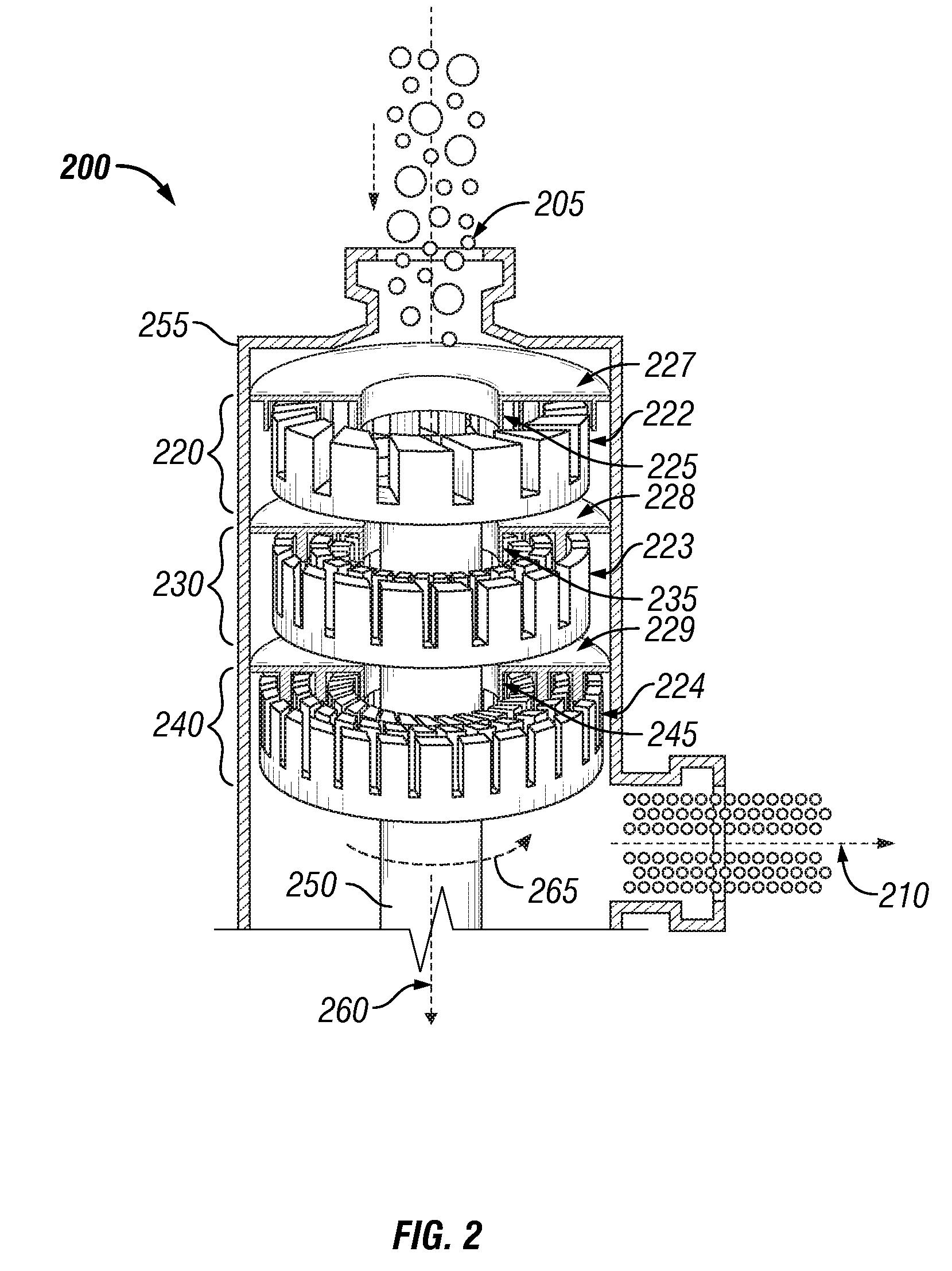
[0020]Overview. The rate of chemical reactions involving liquids, gases and solids depend on time of contact, temperature, and pressure. In cases where it is desirable to react two or more raw materials of different phases (e.g. solid and liquid; liquid and gas; solid, liquid and gas), one of the limiting factors controlling the rate of reaction involves the contact time of the reactants. In the case of heterogeneously catalyzed reactions there is the additional rate limiting factor of having the reacted products removed from the surface of the catalyst to permit the catalyst to catalyze further reactants. Contact time for the reactants and / or catalyst is often controlled by mixing which provides contact with two or more reactants involved in a chemical reaction. In the case of homogeneous reactions, for example liquid / liquid reactions, enhanced mixing may increase the rate or extent of interaction and also homogenize the temperature within the reaction zone(s).

[0021]A system and pr...


PUM

PropertyMeasurementUnit
mean diameteraaaaaaaaaa

Abstract

A method for removing contaminant from feedwater by forming a dispersion comprising bubbles of a treatment gas in a continuous phase comprising feedwater, wherein the bubbles have a mean diameter of less than about 5 μm and wherein the treatment gas is selected from air, oxygen, and chlorine. A method for removing contaminants from a feedwater by subjecting a fluid mixture comprising feedwater and a treatment gas to a shear rate greater than 20,000 s−1 in a high shear device to produce a dispersion of treatment gas in a continuous phase of the feedwater. A system for treating feedwater to remove contaminants therefrom is also presented, the system comprising at least one high shear mixing device comprising at least one generator comprising a rotor and a stator separated by a shear gap; and a pump configured for delivering feedwater and treatment gas to the high shear mixing device.

Description

CROSS-REFERENCE TO RELATED APPLICATIONS[0001]This application claims the benefit under 35 U.S.C. §119(e) of U.S. Provisional Patent Application No. 60 / 946,462 entitled “High Shear Water Treatment Process,” filed Jun. 27, 2007 the disclosure of which is hereby incorporated herein by reference.STATEMENT REGARDING FEDERALLY SPONSORED RESEARCH OR DEVELOPMENT[0002]Not Applicable.BACKGROUND OF THE INVENTION[0003]1. Technical Field[0004]The present invention relates generally to water treatment. More particularly, the present invention relates to a high shear system and process for water treatment. The disclosed system and method may be used to treat waste or raw water containing contaminants whereby the water may be disinfected, stabilized and / or contaminant(s) separated from the water.[0005]2. Background of the Invention[0006]Processes for the recovery of waste water from industrial operations present challenging environmental issues and the government regulates these processes. The impa...

Claims


Application Information

Patent Timeline
Patent Type & Authority Applications(United States)
IPC IPC(8): C02F1/72C02F1/74C02F1/76C02F3/02B01F27/93
CPCC02F1/24C02F1/34C02F1/56C02F1/66C02F2303/04C02F1/74C02F1/76C02F2101/101C02F2101/32C02F1/727
Inventor HASSAN, ABBASBAGHERZADEH, EBRAHIMANTHONY, RAYFORD G.BORSINGER, GREGORYHASSAN, AZIZ
Owner HRD CORP
Why Eureka
Try Eureka