HIGH-k/METAL GATE MOSFET WITH REDUCED PARASITIC CAPACITANCE

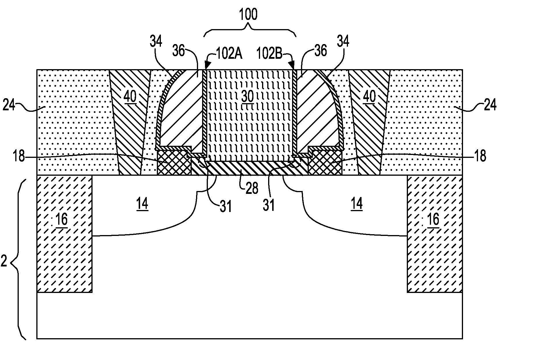
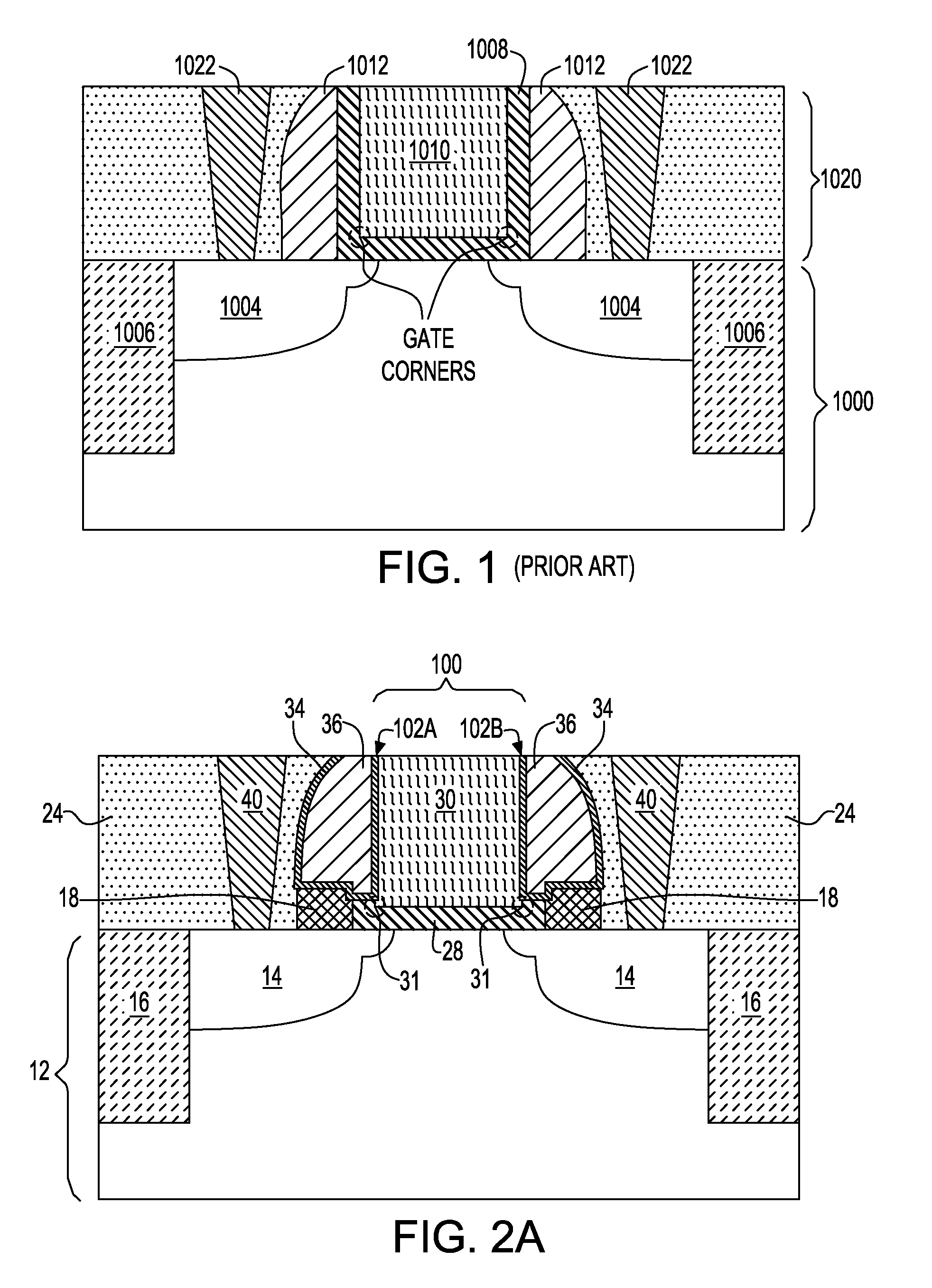
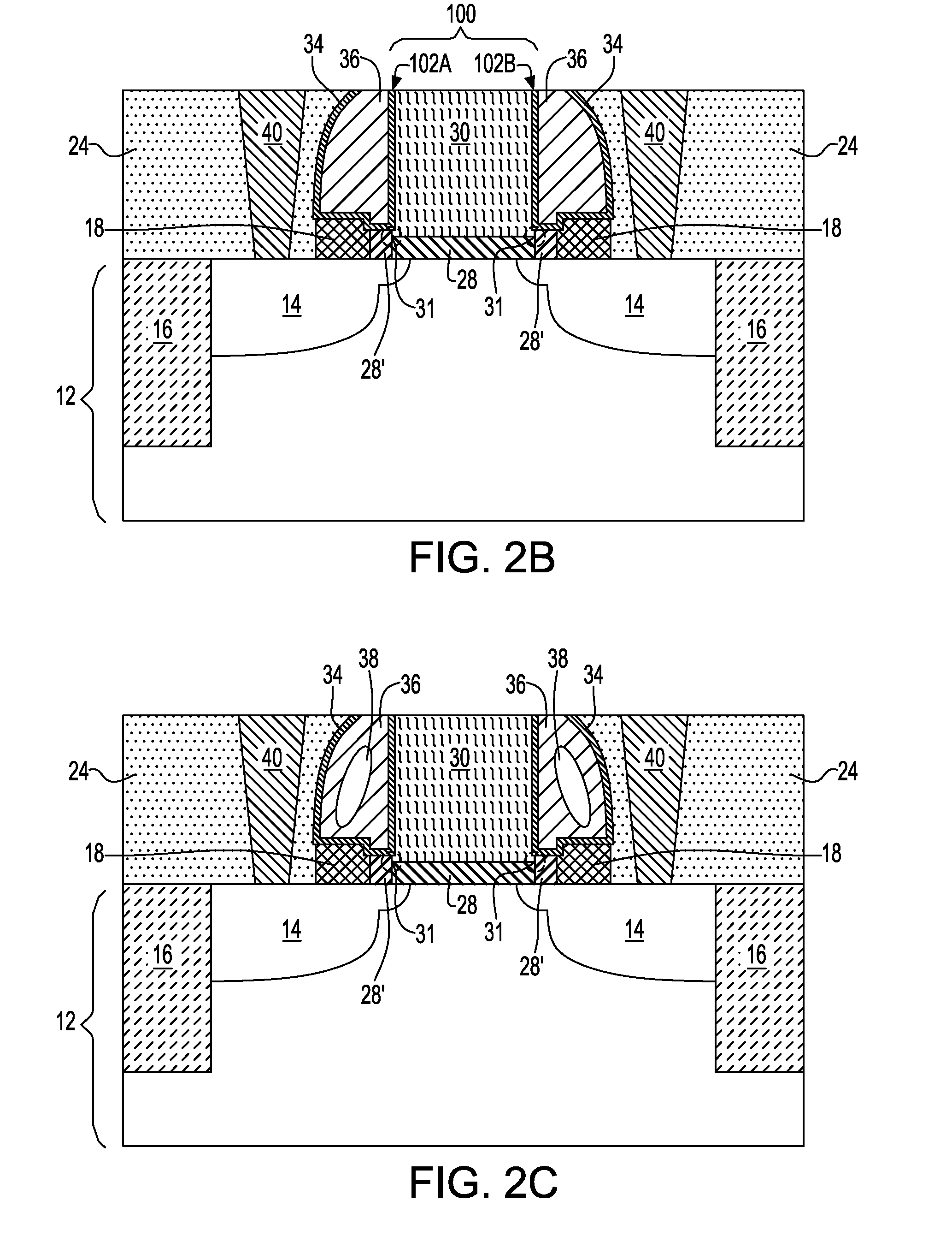
a parasitic capacitance, high-k gate technology, applied in the direction of basic electric elements, electrical apparatus, semiconductor devices, etc., can solve the problems of undetectable high contact-to-gate conductor parasitic capacitance, and high-k gate dielectric at the gate corners (represented by the dotted circle)

Inactive Publication Date: 2009-01-01
TESSERA INC
View PDF20 Cites 255 Cited by
  • Summary
  • Abstract
  • Description
  • Claims
  • Application Information

AI Technical Summary

Benefits of technology

[0026]at least one metal oxide semiconductor field effect transistor (MOSFET) located on a surface of a semiconductor substrate, said at least one MOSFET comprising a gate stack including, from bottom to top, a high-k gate dielectric and a metal-containing gate conductor, said metal-containing gate conductor having gate corners located at a base segment of the metal-containing gate conductor, wherein said metal containing gate conductor has vertical sidewalls devoid of said high-k gate dielectric except at said gate corners;

Problems solved by technology

One severe drawback of a conventional gate replacement process results in the high-k gate dielectric being present not only beneath the metal gate, but also on vertical sidewalls of the metal gate.
The presence of the metal gate 1010 on the vertical sidewalls of the U-shaped high-k gate dielectric 1008 results in an undesired high contact-to-gate conductor parasitic capacitance.
Another problem associated with a high-k gate dielectric is that the high-k gate dielectric at the gate corners (represented by the dotted circle shown in FIG. 1) may not be ideal due to variations in thickness and / or chemical component.
A conventional gate reoxidation process cannot be used to strengthen the high-k gate dielectric at the gate corners because the high-k gate dielectric is sealed by the metal gate and the dielectric spacer.
The non-ideal high-k gate dielectric at the gate corners results in high leakage and poor reliability.

Method used


Image

  • HIGH-k/METAL GATE MOSFET WITH REDUCED PARASITIC CAPACITANCE
  • HIGH-k/METAL GATE MOSFET WITH REDUCED PARASITIC CAPACITANCE
  • HIGH-k/METAL GATE MOSFET WITH REDUCED PARASITIC CAPACITANCE

Examples


Embodiment Construction

[0039]The present invention which provides a high-k gate dielectric / metal-containing MOSFET having at least reduced contact-to-gate conductor parasitic capacitance and a method of fabricating the same, will now be described in greater detail by referring to the following description and drawings that accompany the present application. It is noted that the drawings of the present application are provided for illustrative purposes only and, as such, the drawings are not drawn to scale.

[0040]In the following description, numerous specific details are set forth, such as particular structures, components, materials, dimensions, processing steps and techniques, in order to provide a thorough understanding of the present invention. However, it will be appreciated by one of ordinary skill in the art that the invention may be practiced without these specific details. In other instances, well-known structures or processing steps have not been described in detail in order to avoid obscuring th...


PUM


Abstract

The present invention provides a high-k gate dielectric/metal gate MOSFET that has a reduced parasitic capacitance. The inventive structure includes at least one metal oxide semiconductor field effect transistor (MOSFET) 100 located on a surface of a semiconductor substrate 12. The least one MOSFET 100 includes a gate stack including, from bottom to top, a high-k gate dielectric 28 and a metal-containing gate conductor 30. The metal-containing gate conductor 30 has gate corners 31 located at a base segment of the metal-containing gate conductor. Moreover, the metal-containing gate conductor 30 has vertically sidewalls 102A and 102B devoid of the high-k gate dielectric 28 except at the gate corners 31. A gate dielectric 18 laterally abuts the high-k gate dielectric 28 present at the gate corners 31 and a gate spacer 36 laterally abuts the metal-containing gate conductor 30. The gate spacer 36 is located upon an upper surface of both the gate dielectric 18 and the high-k gate dielectric that is present at the gate corners 31.

Description

FIELD OF THE INVENTION[0001]The present invention relates to a semiconductor structure and a method of fabricating the same. More particularly, the present invention relates to a metal oxide semiconductor field effect transistor (MOSFET) including a high dielectric constant (k) gate dielectric and a metal-containing gate conductor that has reduced parasitic capacitance. The present invention also provides a method of fabricating such a MOSFET.BACKGROUND OF THE INVENTION[0002]In the semiconductor industry, a gate stack including a high-k gate dielectric (a gate dielectric having a dielectric constant of greater than 4.0, typically greater than 7.0) and a metal gate is one of the most promising options for continuing complementary metal oxide semiconductor (CMOS) scaling.[0003]One of the process schemes for fabricating a high-k / metal gate MOSFET is a replacement gate method. In a replacement gate process, a MOSFET can be fabricated using a sacrificial gate electrode. In such a process...

Claims


Application Information

Patent Timeline
Patent Type & Authority Applications(United States)
IPC IPC(8): H01L29/78H01L21/3205
CPCH01L21/28194H01L29/42368H01L29/4983Y10S438/926H01L29/6653H01L29/66545H01L29/66583H01L29/517H01L29/4991H01L29/045H01L29/165H01L29/66628H01L29/66636H01L29/66795H01L29/7834H01L29/7848H01L29/785H01L2924/13091
Inventor CHENG, KANGGUO
Owner TESSERA INC
Why Eureka
Try Eureka