Embedded Heat Pipe In A Hybrid Cooling System

a heat pipe and hybrid technology, applied in the field of systems, can solve the problems of high speed operation, large amount of heat generated by the gpu during operation, and large amount of unwanted acoustic noise, and achieve the effects of increasing the heat transfer surface area, reducing the amount of heat generated, and reducing the amount of noise generated

Active Publication Date: 2009-01-01
NVIDIA CORP
View PDF7 Cites 13 Cited by
  • Summary
  • Abstract
  • Description
  • Claims
  • Application Information

AI Technical Summary

Benefits of technology

[0018]One embodiment of a system for cooling a heat-generating device includes a base adapted to be coupled to the heat-generating device; a housing coupled to the base; a liquid channel formed between the base and the housing, wherein a heat transfer liquid may be circulated through the liquid channel to remove heat generated by the heat-generated device; and a heat pipe disposed within the liquid channel, wherein the heat pipe increases the heat transfer surface area to which the heat transfer liquid is exposed. Among other things, the heat pipe advantageously increases the heat transfer surface area to which the heat transfer liquid is exposed and efficiently spreads the heat generated by the heat-generating device over that heat transfer surface area. The result is enhanced heat transfer through the liquid channel relative to prior art cooling systems.

Problems solved by technology

Because the computational requirements of GPU 216 are typically quite substantial, GPU 216 tends to generate a large amount of heat during operation.
One drawback of these conventional blower / fan cooling systems is that, as processors become more powerful and generate more heat, the fan has to be operated at very high speeds to generate the airflow through the air channels and over the heat sink necessary to cool the processor.
High speed operation tends to produce a substantial amount of unwanted acoustic noise, which is annoying to users of a computer.
Also, in some instances, these types of conventional cooling systems may not even be able to meet the heat dissipation requirements of certain high-performance processors.
Further compounding these issues is the fact that, while processors are becoming more powerful, the available space for cooling systems within computing devices is generally not increasing.
However, typical liquid cooling systems are driven by large pumps, which are prone to frequent failure and tend to consume a great deal of power.
Moreover, such systems tend to use large quantities of liquid, circulating at a high flow rate, and therefore must be frequently replenished or replaced.
One drawback to using the hybrid cooling system 300 is that, when the pump is inoperative and no heat transfer liquid is circulated through the liquid channel 312, a substantial amount of cooling capacity is lost because air cooling provided by the fansink 302 is limited to the air channels 310, 322 that are not obstructed by the liquid channel 312.
In such configurations, when the pump is inoperative and no heat transfer liquid is circulated through the liquid channel, the standing liquid in the liquid channel acts like an insulator and retards the heat transfer between the processor or other heat-generating device and the walls of the fansink air channels, substantially decreasing the cooling efficiency of the hybrid cooling system.
In addition, when such a “stacked” hybrid cooling system is installed in a peripheral component interconnect (PCI) slot, height restrictions become a concern.
Reducing the height of the air channels reduces the effective heat transfer area of the air channels, further decreasing the cooling efficiency of the hybrid cooling system.

Method used


Image

  • Embedded Heat Pipe In A Hybrid Cooling System
  • Embedded Heat Pipe In A Hybrid Cooling System
  • Embedded Heat Pipe In A Hybrid Cooling System

Examples


Embodiment Construction

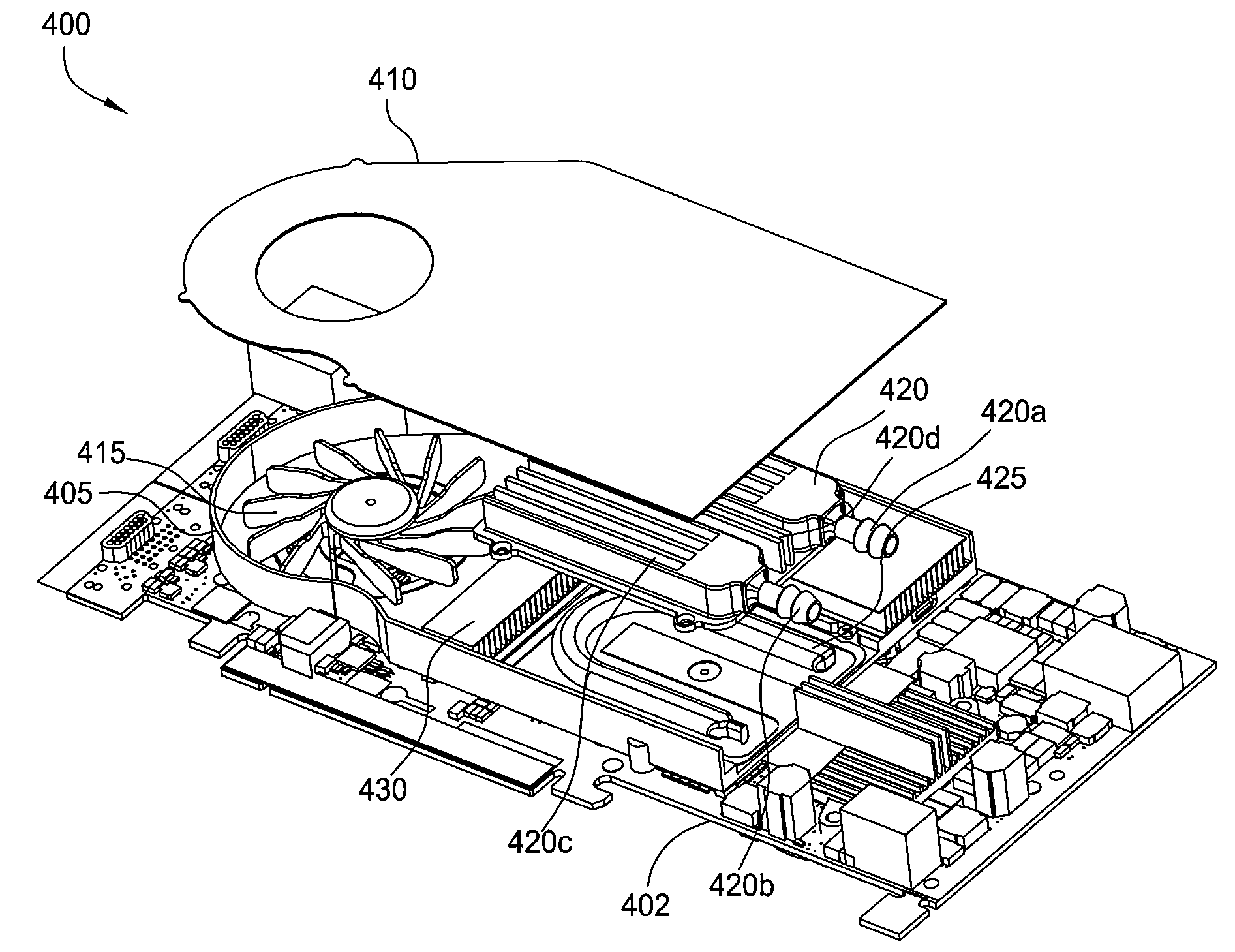
[0024]FIG. 4A is an exploded isometric view of a hybrid cooling system 400, according to one embodiment of the present invention. Hybrid cooling system 400 is configured to be thermally and structurally coupled to a printed circuit board (PCB), such as the graphics card 402 or the graphics card 202 of FIG. 2, and implemented with a computer system, such as the computer system 200 of FIG. 2. Mounted on a top side, the graphics card 402 includes GPU 416 (more clearly depicted in FIG. 4C) and other components, such as memory units (not shown) and a power supply (not shown). Preferably, the graphics card 402 is configured to connect to a computer system via a standard peripheral component interconnect PCI slot. Further, the hybrid cooling system 400 is configured so that when it is mounted to the graphics card 402, the cooling system 400 and the graphics card 402 will fit substantially within one standard PCI slot of a computer system. In alternate embodiments, the hybrid cooling system...


PUM


Abstract

One embodiment of a system for cooling a heat-generating device includes a base adapted to be coupled to the heat-generating device, a housing coupled to the base, a liquid channel formed between the base and the housing, where a heat transfer liquid may be circulated through the liquid channel to remove heat generated by the heat-generated device, and a heat pipe disposed within the liquid channel, where the heat pipe increases the heat transfer surface area to which the heat transfer liquid is exposed. Among other things, the heat pipe advantageously increases the heat transfer surface area to which the heat transfer liquid is exposed and efficiently spreads the heat generated by the heat-generating device over that heat transfer surface area. The result is enhanced heat transfer through the liquid channel relative to prior art cooling systems.

Description

CROSS-REFERENCE TO RELATED APPLICATIONS[0001]This application is a continuation of U.S. patent application Ser. No. 11 / 294,825 entitled, “EMBEDDED HEAT PIPE IN A HYBRID COOLING SYSTEM,” filed Dec. 5, 2005 and having Attorney Docket No. NVDA / P002015. The subject matter of this related application is hereby incorporated herein by reference.BACKGROUND OF THE INVENTION[0002]1. Field of the Invention[0003]This invention relates generally to systems used to cool computer hardware and more particularly to an embedded heat pipe in a hybrid cooling system.[0004]2. Description of the Background Art[0005]FIG. 1 is an isometric view illustrating a prior art cooling system 100 used to cool heat-generating electronic devices in a computer system, such as a graphics processing unit (GPU). As shown, cooling system 100 characteristically includes a blower / fan 106, fins 109 and a bottom plate 111. Typically, cooling system 100 is thermally coupled to the GPU, for example using thermal adhesive or gre...

Claims


Application Information

Patent Timeline
Patent Type & Authority Applications(United States)
IPC IPC(8): H01L23/34H05K7/20
CPCF28D1/024F28D1/0408F28D7/14F28D15/04H01L23/427H01L2924/0002H01L23/467H01L2924/00
Inventor STEFANOSKI, ZORAN
Owner NVIDIA CORP
Why Eureka
Try Eureka