
Mounting Process and Mounting Unit for Doors on Vehicle Bodies

a technology for mounting units and doors, which is applied in the direction of vehicle bodies, roofs, monocoque constructions, etc., can solve the problems of insufficient quality requirements imposed on the optical appearance of vehicles, and achieve the effect of better mounting techniques

Inactive Publication Date: 2009-01-01
KUKA SYSTEMS
View PDF1 Cites 4 Cited by
  • Summary
  • Abstract
  • Description
  • Claims
  • Application Information

AI Technical Summary

Benefits of technology

[0004]The object of the present invention is to show a better mounting technique.
[0005]The mounting technique according to the invention has the advantage that on each side of the vehicle, the side doors located there can be mounted together and in a mutually coordinated manner with one another and with the vehicle body. Due to the possibility of mutual alignment, better and more uniform appearance of the vehicle can be achieved. Visible gaps and other design lines can be presented in an optimal form. In addition, suitable allowances can be taken into account for the later final mounting of the finished and heavier doors in an accurately fitting manner in the case of the initial mounting of the still bare side doors.
[0006]The mounting of the doors from the interior space of the body with a corresponding, suitable fixing means has the advantage that fixation of the side doors, preferably provided with door hinges in advance, can be carried out in the closed position in the door cutout of the vehicle body. This is the position of the door that is determined by the positioning means and is decisive for the optical appearance of the finished vehicle. The mounting technique being claimed also offers here especially suitable embodiments of the door hinge with bent hinge flanges and with body parts intended for the fixation, especially the door pillars. The outside mounting of the hinge flanges on the door pillars is especially suitable and facilitates fixation from the interior space of the body.
[0007]It is, furthermore, favorable in the case of the mounting technique being claimed that the positioning and fixing means, which preferably comprise robots each, can be arranged such that they do not mutually hinder each other. It is especially advantageous for this if the fixing robots are arranged on the other side of the vehicle and extend with their fixing tools, e.g., screwing or welding tools, through the adjacent door cutout or possibly the window cutout of an already mounted side door into the interior space of the body and reach the fixing sites of the side doors to be mounted, which said fixing sites are located opposite.
[0009]The premounting of door hinges on the side doors has the advantage that any tolerances on the body parts can be better absorbed and compensated. By means of the measuring and aligning device used for the correctly fitting positioning of the door, or another measuring device, it is possible to check during and after the mounting of the door whether the premounting of the door hinges on the side door was correct and whether the existing tolerances were absorbed correctly. If deviations are detected in this connection and a trend is seen in the development of the tolerances on the basis of a statistical survey and analysis, this can be counteracted for the subsequent doors in a specific manner by a corresponding feedback to the premounting unit and a corresponding precompensation of the dimensional imperfections detected.

Problems solved by technology

This has proved to be insufficient in respect to the increasing quality requirements imposed on the optical appearance of vehicles.

Method used


Image

  • Mounting Process and Mounting Unit for Doors on Vehicle Bodies
  • Mounting Process and Mounting Unit for Doors on Vehicle Bodies
  • Mounting Process and Mounting Unit for Doors on Vehicle Bodies

Examples


Embodiment Construction

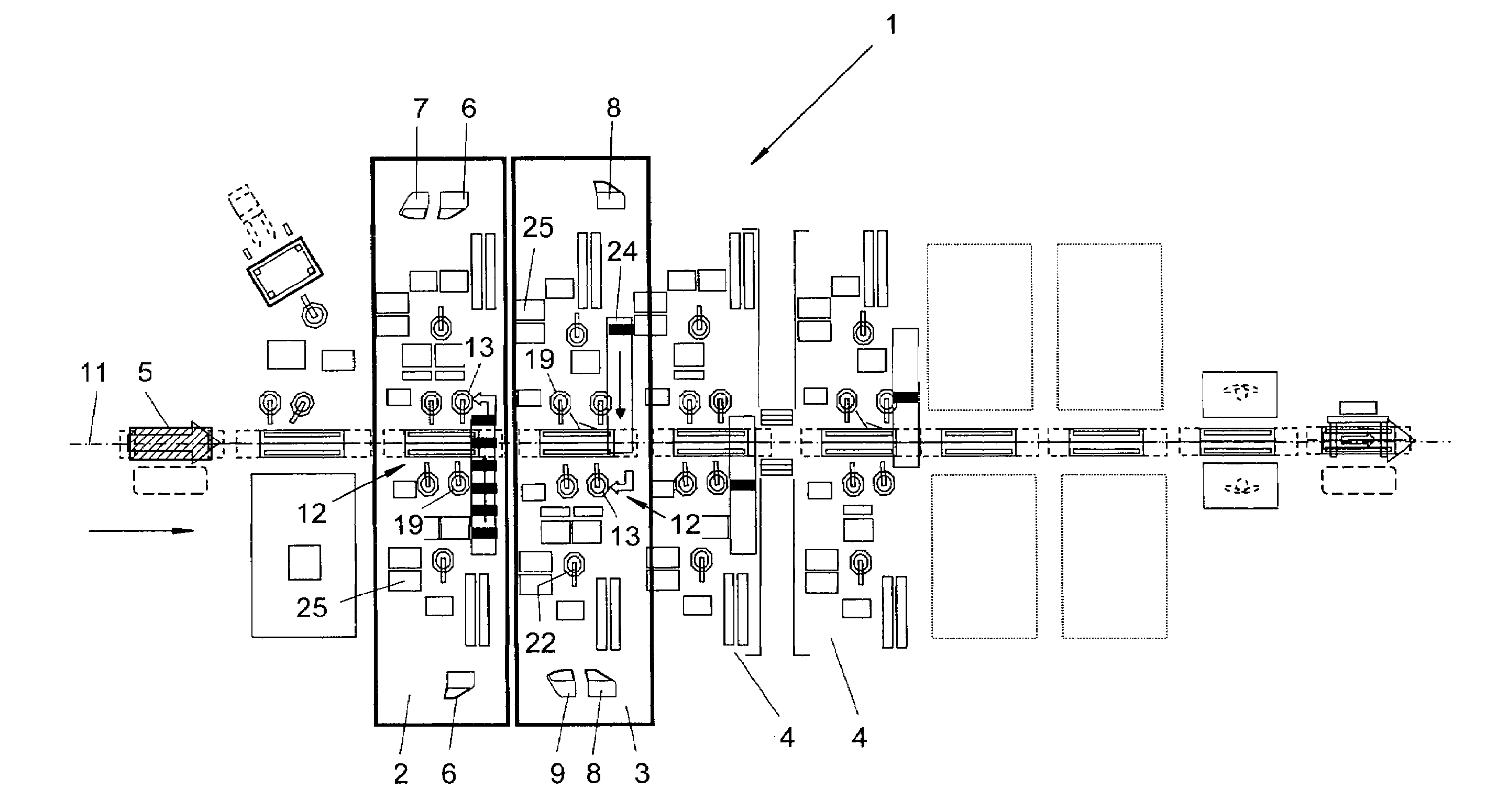
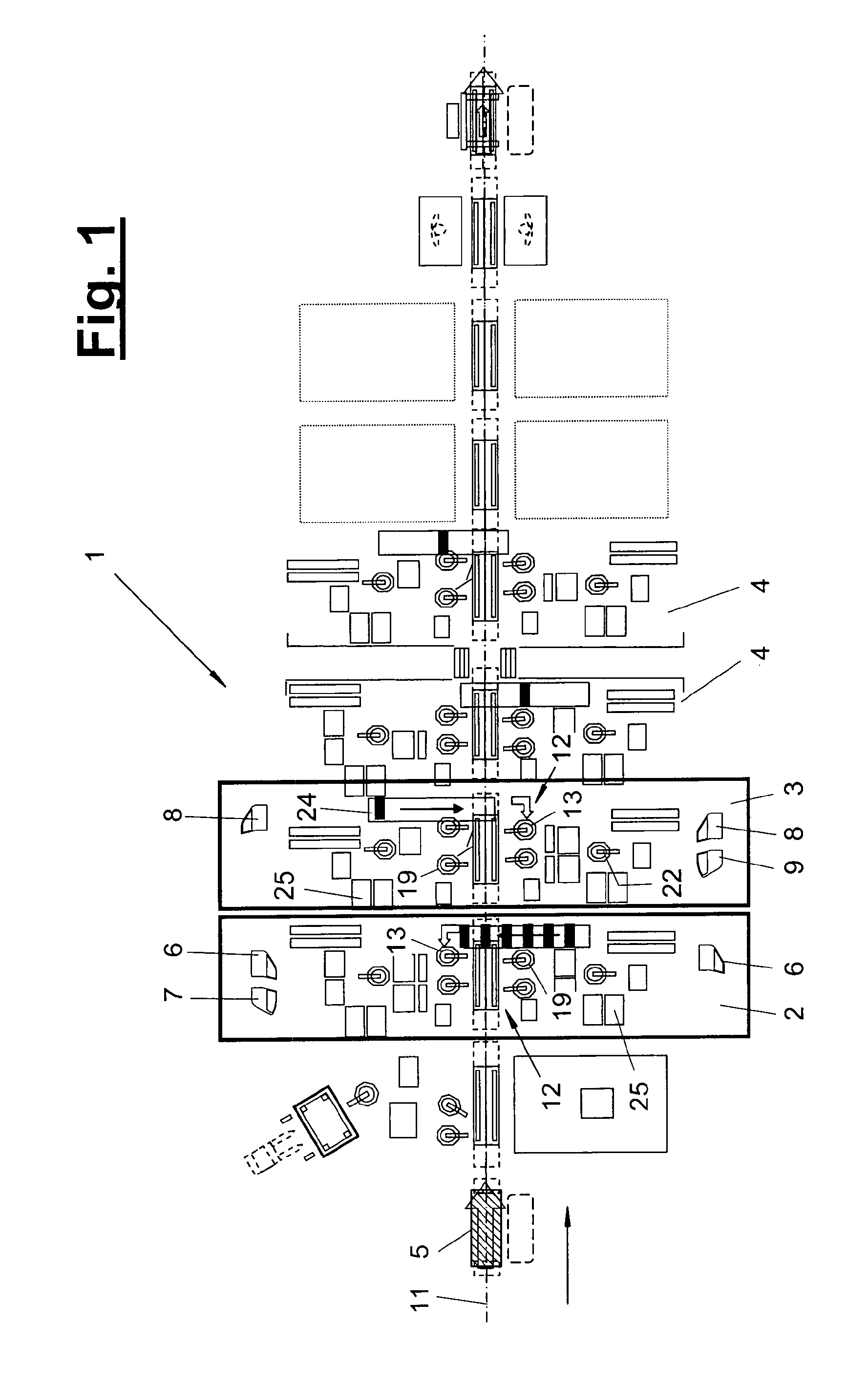
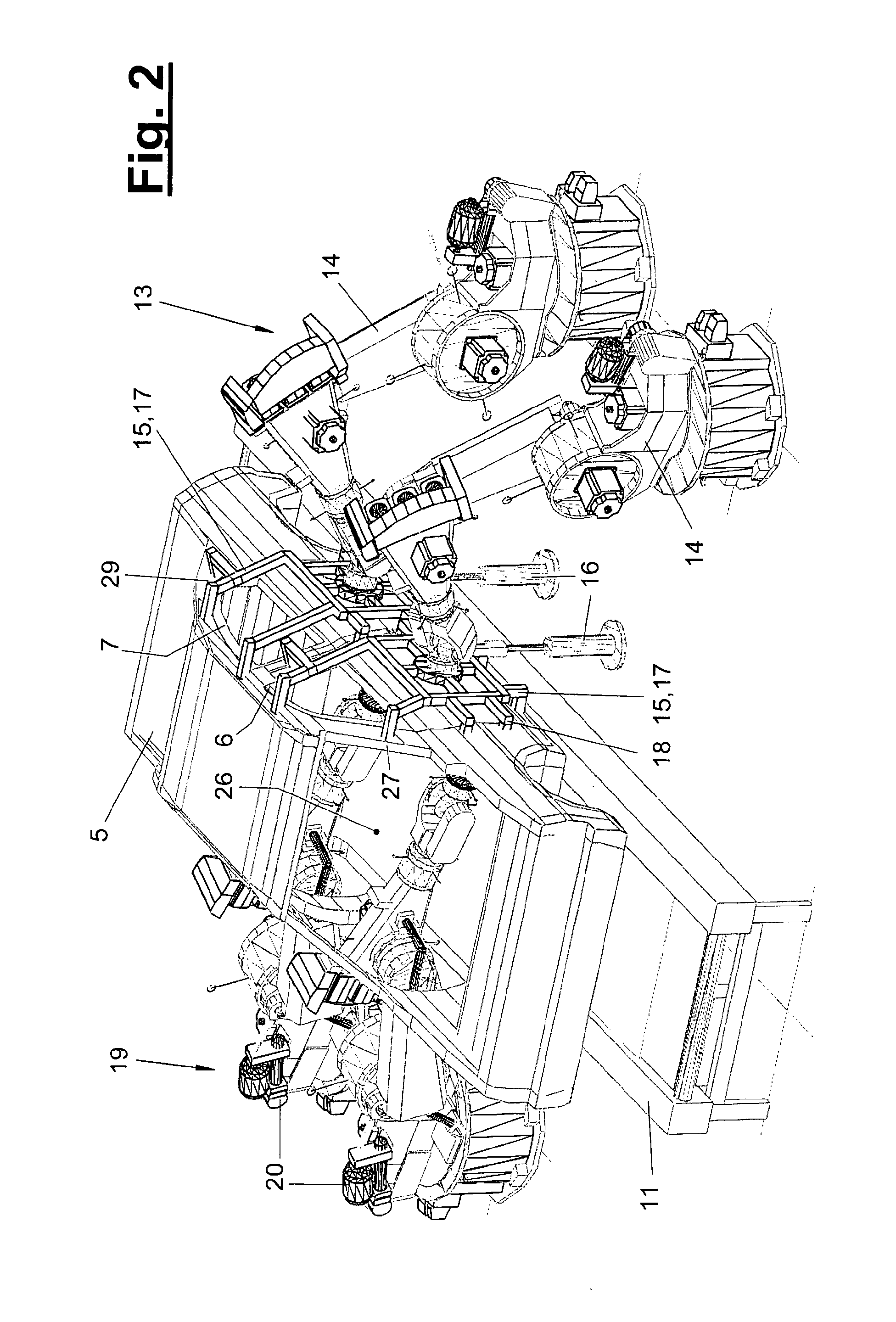
[0018]Referring to the drawings in particular, the present invention pertains to a mounting technique for the side-by-side mounting of side doors (6, 7, 8, 9) on a vehicle body (5). This pertains specifically to the mounting unit (1) provided herefor and, further, also to the 15 mounting process as well as the correct design of the vehicle parts, especially the vehicle body (5), the side doors (6, 7, 8, 9) and the door hinges (34) for the mounting.

[0019]In a schematic top view, FIG. 1 shows a mounting unit (1) for vehicle bodies (5), which are fed on a conveyor (11) along a transfer line and are transported through a plurality of stations (2, 3, 4). The vehicle body (1) is a body shell of vehicles, which comprises at least side walls with cross connections via a roof part and / or an underbody. Other body parts, such as crossrail for the rear shelf, the front wall and the rear wall of the body, etc., may likewise be present. FIGS. 2 and 3 show schematic view of such a vehicle body (5)...


PUM


Abstract

The invention relates to a method and a system for mounting at least four lateral doors (6, 7, 8, 9) on a vehicle body (5) comprising door holes (30, 31). Several lateral doors (6, 7, 8, 9) are mounted jointly on one side of the vehicle in an assembly station (2, 3) and are jointly retained, measured, and aligned by a positioning mechanism (13) encompassing a measuring and aligning device (17). Preferably, the door is fastened from the inside of the body by means of a fastening device (19) located on the opposite side of the vehicle.

Description

CROSS REFERENCE TO RELATED APPLICATIONS[0001]This application is a U.S. National Phase application of International Application PCT / EP2006 / 011979 and claims the benefit of priority under 35 U.S.C. § 119 of German patent application DE 20 2005 019 619.3 filed Dec. 13, 2005, the entire contents of which are incorporated herein by reference.FIELD OF THE INVENTION[0002]The present invention pertains to a mounting process and a mounting unit for the mounting of at least four side doors on a vehicle body.BACKGROUND OF THE INVENTION[0003]It is known and common in practice to mount the front side doors in pairs on the left and right and subsequently the rear side doors in pairs on the left and right on the vehicle body in the case of four-door vehicle bodies, and this order may also be reversed. As a result, the front and rear side doors are mounted offset in time on each side of the vehicle. This has proved to be insufficient in respect to the increasing quality requirements imposed on the...

Claims


Application Information

Patent Timeline
Patent Type & Authority Applications(United States)
IPC IPC(8): B62D65/06
CPCB62D65/06
Inventor EMERICH, BRUNOHESSE, JOHANNKOLLMAR, THOMAS
Owner KUKA SYSTEMS
Learn More