Electronic Method for Starting a Compressor

a compressor and electric motor technology, applied in the direction of motor/generator/converter stopper, dynamo-electric converter control, dynamo-electric gear control, etc., can solve the problem of motor stalling when the start capacitor relay is turned on, high temperature, and damage to mechanical stresses

Inactive Publication Date: 2009-01-01
CARRIER CORP
View PDF1 Cites 30 Cited by
  • Summary
  • Abstract
  • Description
  • Claims
  • Application Information

AI Technical Summary

Benefits of technology

[0007]A motor starting apparatus includes a motor starting relay to switch a motor starting capacitor into a motor circuit across a run capacitor. The motor starting capacitor increases an alternating current (AC) current flow through a motor winding to start the motor. The motor starting apparatus also includes a system control to control the motor starting relay and at least one contactor to apply power to the motor starting apparatus. The system control includes an electronic voltage measurement circuit to measure a winding voltage of the motor winding. The system control also includes a microprocessor to run an algorithm that causes the system control to switch the starting capacitor out of the motor circuit when a measured winding voltage exceeds a winding voltage threshold.
[0008]A method to start a motor includes the steps of: providing a mo

Problems solved by technology

If the start capacitor relay is opened too soon before the motor has achieved a sustainable shaft rotation speed, the motor will stall when the start capacitor relay is opened.
If the start capacitor relay is opened too late, the winding currents and voltages can become excessively high potentially causing high temperatures, damaging mechanical stresses, and insulation breakdown.
The accuracy of potential relays is only about 20 VAC which limits the ability to accurately time the opening of the start capacitor contactor.
The problem is that the optimal conditions for opening th

Method used


Image

  • Electronic Method for Starting a Compressor
  • Electronic Method for Starting a Compressor
  • Electronic Method for Starting a Compressor

Examples


example

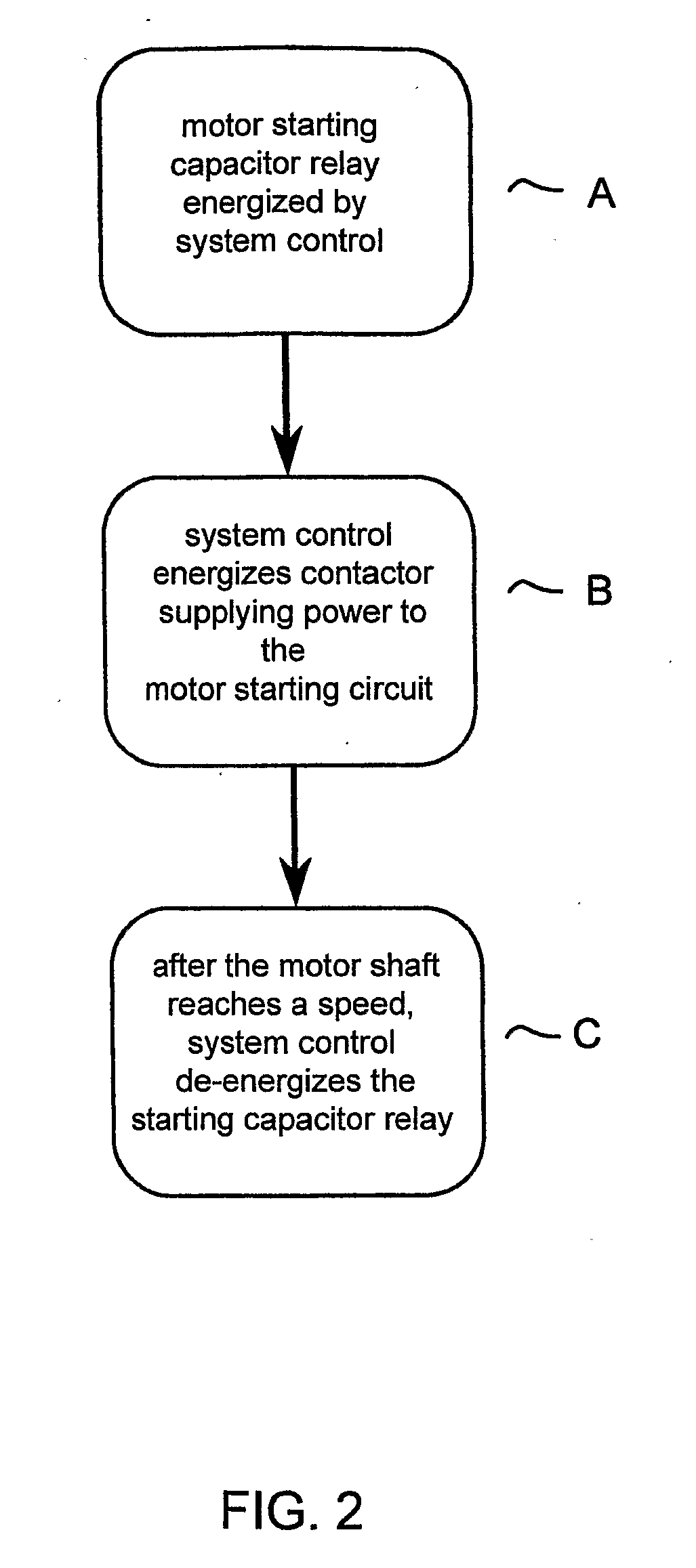
[0029]FIGS. 4A and 4B show a flow chart (one flow chart drawn across two drawing sheets) of an algorithm that can run on a microprocessor on system control in a preferred embodiment using both voltage thresholds and time delays as previously described. The sequence of steps begins at “start”. A counter, that can be used to monitor the number of successive start attempts, is initialized to “0”. A motor capacitor start relay is energized and then after 1 second, a motor start contactor applies electrical power to a motor start circuit. The system control monitors a motor winding by taking a voltage measurement. The voltage measurement is compared to a winding voltage threshold. If the voltage measurement indicates that the motor is up to a threshold rotor speed, as indicated by reaching the threshold voltage, the start relay is de-energized and the compressor runs normally after a “good” start. On the other hand, if the voltage measurement is below the threshold voltage, the algorithm...


PUM


Abstract

A motor starting apparatus (10) includes a motor starting relay (112) to switch a motor starting capacitor (110) into a motor circuit across a run capacitor (111). The system control (116) includes an electronic voltage measurement circuit to measure a winding voltage (113, 114) of the motor winding (102, 103). The system control (116) also includes a microprocessor to run an algorithm that causes the system control to switch the starting capacitor (110) out of the motor circuit when a measured winding voltage (113, 114) exceeds a winding voltage threshold. A method to start a motor includes the steps of determining a motor winding voltage (113, 114) threshold; closing the motor starting capacitor relay (112) when needed; closing a contactor (108, 109) to supply power to the motor starting apparatus and the motor circuit; measuring a winding voltage (113, 114); comparing the measured winding voltage (113, 114) to the voltage threshold; and opening the starting capacitor relay (112) when measured winding voltage (113, 114) exceeds the voltage threshold indicating that the motor has been started.

Description

FIELD OF THE INVENTION[0001]This invention relates generally to a method and apparatus to start a capacitor-start capacitor-run motor, and more particularly to start a reversible CSCR motor used to drive a compressor.BACKGROUND OF THE INVENTION[0002]An electric motor is typically used to drive the shaft of a compressor used in heating ventilation and air conditioning (HVAC) systems. The electric motor can be an alternating current (AC) capacitor-start capacitor-run (CSCR) motor. CSCR motors can conveniently run on single phase AC power, such as between the lines of a standard 230 V AC commercial or residential power system. A CSCR AC motor has two windings, a “run” winding and a “start” winding. Motion is created in the rotor of the motor by causing a phase difference between the AC electrical currents in the two windings. This phase difference is caused by introducing a capacitor in series with one of the windings.[0003]A CSCR motor is started by momentarily introducing a larger ca...

Claims


Application Information

Patent Timeline
IPC IPC(8): H02P25/04
CPCF04B49/02H02P1/44H02H7/0816
Inventor MILLS, JR., EUGENE L.SHAH, RAJENDRA K.TURNER, LYNN A.
Owner CARRIER CORP
Why Eureka
Try Eureka