Electrical filters with improved intermodulation distortion

a technology of intermodulation distortion and electric filters, applied in waveguides, instruments, computing, etc., can solve the problems of affecting the size and cost of resonators for a given, corresponding compromise in filter steepness or selectivity, and conductors with inherent lossiness

Inactive Publication Date: 2009-01-01
RESONANT
View PDF11 Cites 58 Cited by
  • Summary
  • Abstract
  • Description
  • Claims
  • Application Information

AI Technical Summary

Benefits of technology

[0022]In accordance with a third aspect of the present inventions, a radio frequency (RF) network is provided. The filter network comprises a band-pass filter configured for creating a passband, and a band-stop filter that includes a plurality of resonant elements coupled together to form a stopband. In one embodiment, the band-stop filter comprises a thin-film quasi-lumped element structure (e.g., made of high temperature superconductor (HTS) material, although other types of filters can be used for the band-stop filter.
[0023]At least two of the resonant elements have third order intermodulation distortion (IMD) components (third order IMD products 2f2−f1 and 2f1−f2) different from each other, such that the third order IMD components are asymmetrical about the stopband. In one embodiment, the th

Problems solved by technology

In particular, such electrical filters are used to select desired electrical signal frequencies from an input signal by passing the desired signal frequencies, while blocking or attenuating other undesirable electrical signal frequencies.
This requirement for low resistance tends to drive the size and cost of the resonators for a given technology.
In most filter technologies, achieving a low insertion loss requires a corresponding compromise in filter steepness or selectivity.
These conductors have inherent lossiness, and as a result, the circuits formed from them have varying degrees of loss.
For resonant circuits, the loss is particularly critical.
The filters required are often quite complex with perhaps twelve or more resonators along with some cross couplings.
Yet the available size of usable substrates is generally limited.
In the case of narrow-band microstrip filters (e.g., bandwidths of the order of 2 percent, but more especially 1 percent or less), this size problem can become quite severe.
IMD is an undesirable phenomenon that occurs when two or more signals of different frequencies are present at the input of a non-linear device, thereby generating spurious emissions at frequencies different from the desired harmonic frequencies of the filter.
If

Method used


Image

  • Electrical filters with improved intermodulation distortion
  • Electrical filters with improved intermodulation distortion
  • Electrical filters with improved intermodulation distortion

Examples


Embodiment Construction

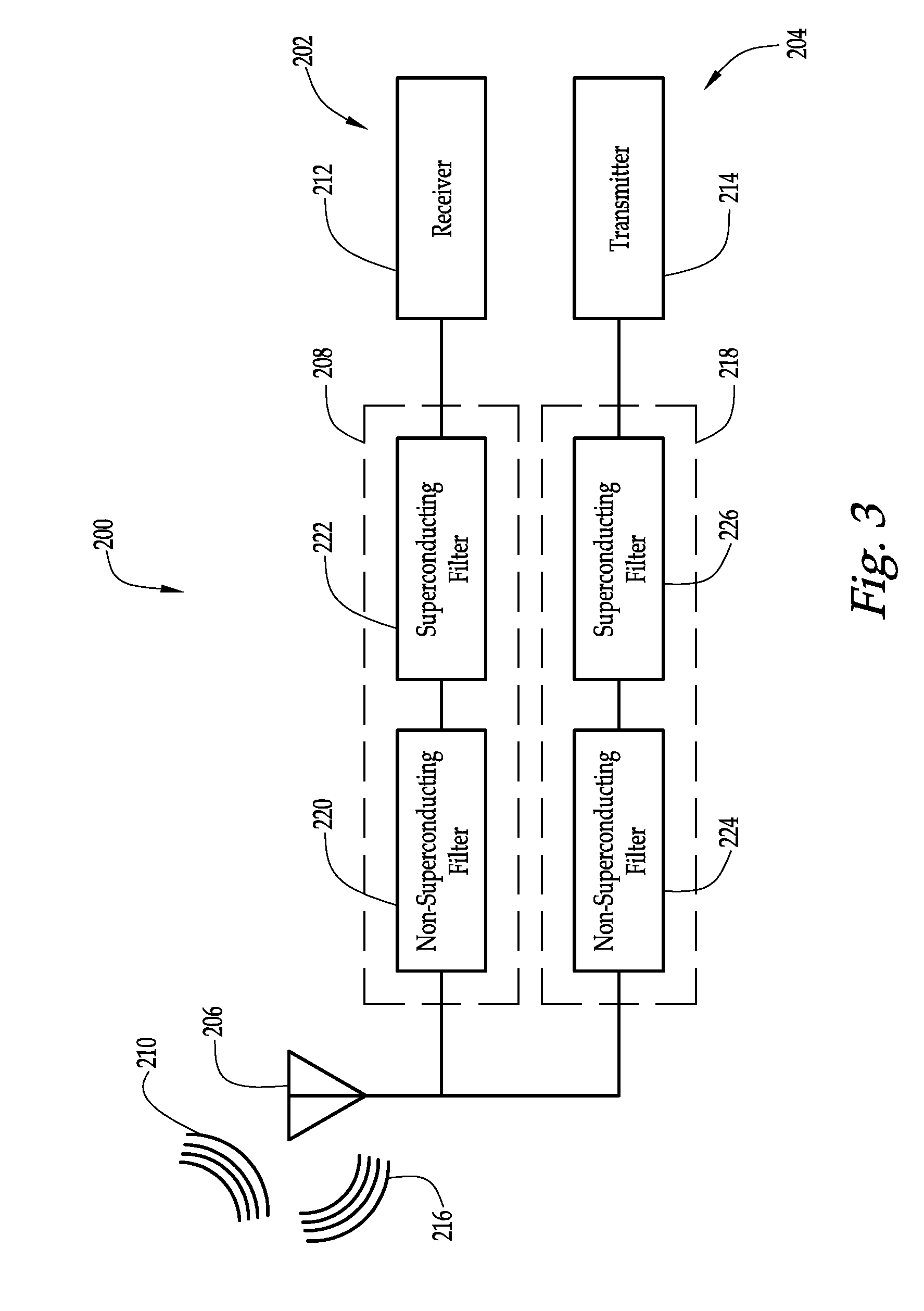
[0043]Referring to FIG. 3, one embodiment of a radio frequency (RF) communications system 200 constructed in accordance with the present inventions will now be described. The communications system 200 may be used in, for example, a base station. The communications system 200 generally comprises a front-end receiver system 202, a transmit system 204, and an antenna 206 shared by the receiver and transmit systems 202, 204.

[0044]The receiver system 202 comprises a filter network 208 for filtering RF signals 210 received by the antenna 206, and a receiver 212 for receiving the filtered RF signals 210 from the filter network 208. The filter network 208 is used to selectively pass the received RF signals 210 within a designated passband to the receiver 212, while filtering out interfering signals (which typically include RF signals transmitted by other communications systems and co-located transmission signals generated by the transmit system 204) located outside the operating frequency o...


PUM


Abstract

A method of constructing a band-stop filter comprises designing a band-stop filter including a signal transmission path, resonant elements disposed along the signal transmission path, and non-resonant elements coupling the resonant elements together to form a stopband having transmission zeroes corresponding to respective frequencies of the resonant elements. The method further comprises changing the order in which the resonant elements are disposed along the signal transmission path to create different filter solutions, computing a performance parameter for each filter solution, comparing the performance parameters to each other, selecting one of the filter solutions based on this comparison, and constructing the band-stop filter using the selected filter solution. Another RF band-stop filter comprises resonant elements coupled together to form a stopband, wherein at least two of the resonant elements have third order IMD components different from each other, such that the IMD components are asymmetrical about the stopband.

Description

RELATED APPLICATION[0001]This application claims priority from U.S. Provisional Patent Application Ser. No. 60 / 937,355, filed Jun. 27, 2007, which is expressly incorporated herein by reference.FIELD OF THE INVENTION[0002]The present inventions generally relate to microwave circuits, and in particular, microwave filters.BACKGROUND OF THE INVENTION[0003]Electrical filters have long been used in the processing of electrical signals. In particular, such electrical filters are used to select desired electrical signal frequencies from an input signal by passing the desired signal frequencies, while blocking or attenuating other undesirable electrical signal frequencies. Filters may be classified in some general categories that include low-pass filters, high-pass filters, band-pass filters, and band-reject filters, indicative of the type of frequencies that are selectively passed by the filter. Further, filters can be classified by type, such as Butterworth, Chebyshev, Inverse Chebyshev, a...

Claims


Application Information

Patent Timeline
IPC IPC(8): H01P1/20G06F17/50
CPCH03H7/01H01P1/20
Inventor TSUZUKI, GENICHIWILLEMSEN, BALAM A.
Owner RESONANT
Why Eureka
Try Eureka