Electric coil and core cooling method and apparatus

a technology of electric coils and cores, applied in the direction of magnets, inductances, magnetic bodies, etc., can solve the problems of reducing the thermal resistance at the interfaces of components, and achieve the effect of improving cooling and heat distribution in power modules

Inactive Publication Date: 2009-01-01
ROCKWELL AUTOMATION TECH
View PDF4 Cites 31 Cited by
  • Summary
  • Abstract
  • Description
  • Claims
  • Application Information

AI Technical Summary

Benefits of technology

[0001]The present invention relates generally to the field of power electronic devices and their thermal management. More particularly, the invention relates to a technique for improving cooling and heat distribution in power modules.

Problems solved by technology

The contact may close this and reduce the thermal resistance at the interfaces of the components, and thus promote heat transfer from the magnetic core and the conductive coil to the cooling element.

Method used


Image

  • Electric coil and core cooling method and apparatus
  • Electric coil and core cooling method and apparatus
  • Electric coil and core cooling method and apparatus

Examples


Embodiment Construction

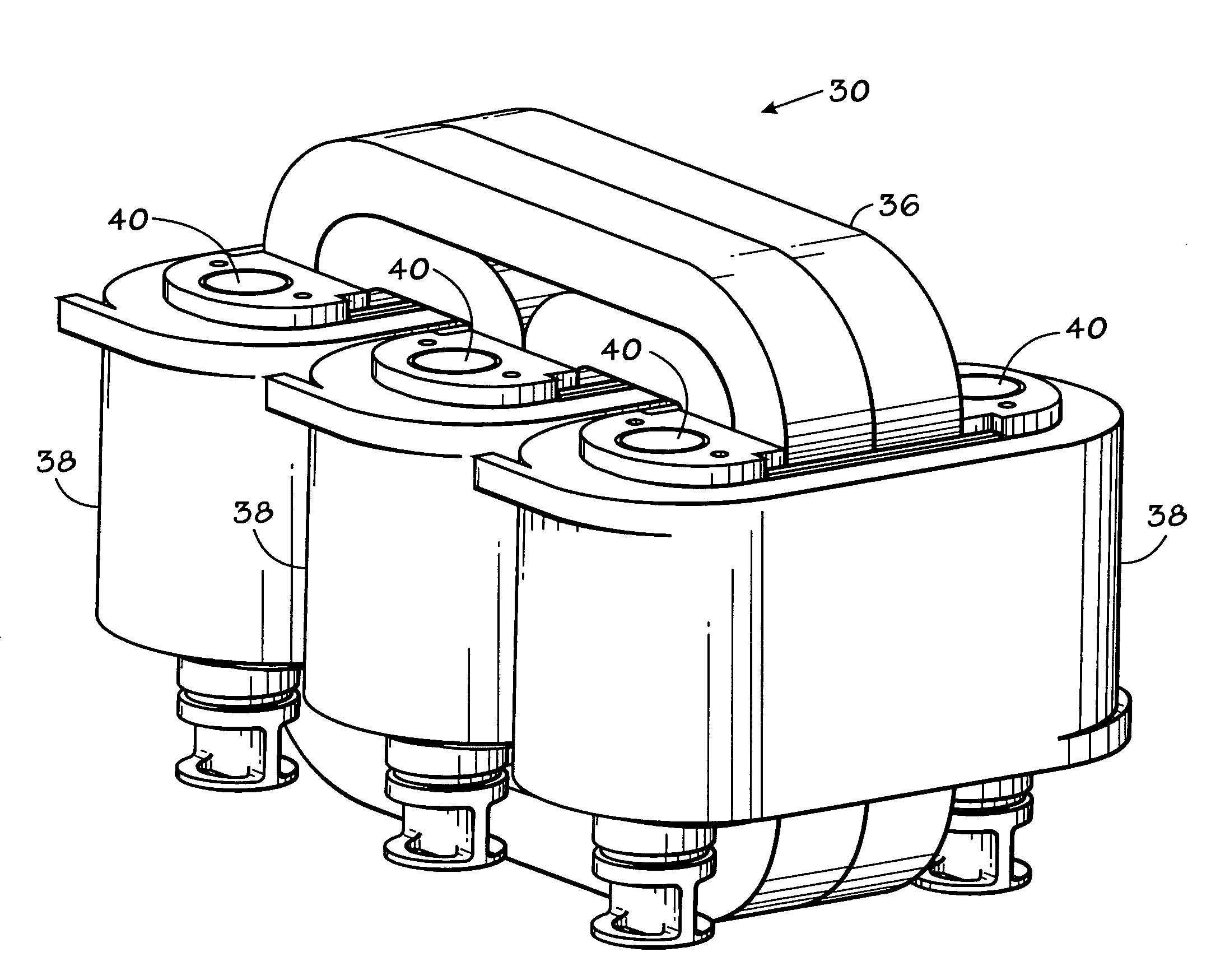
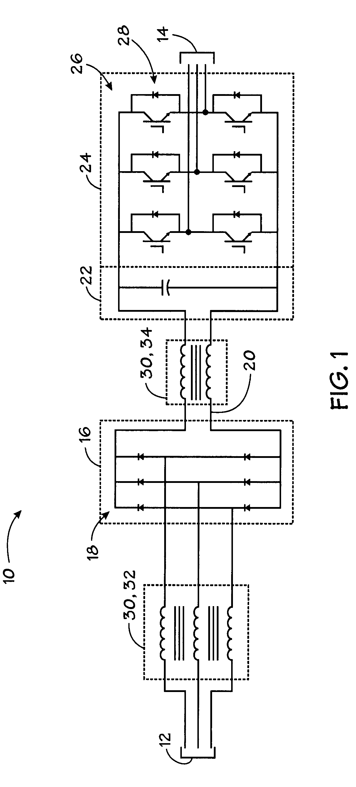
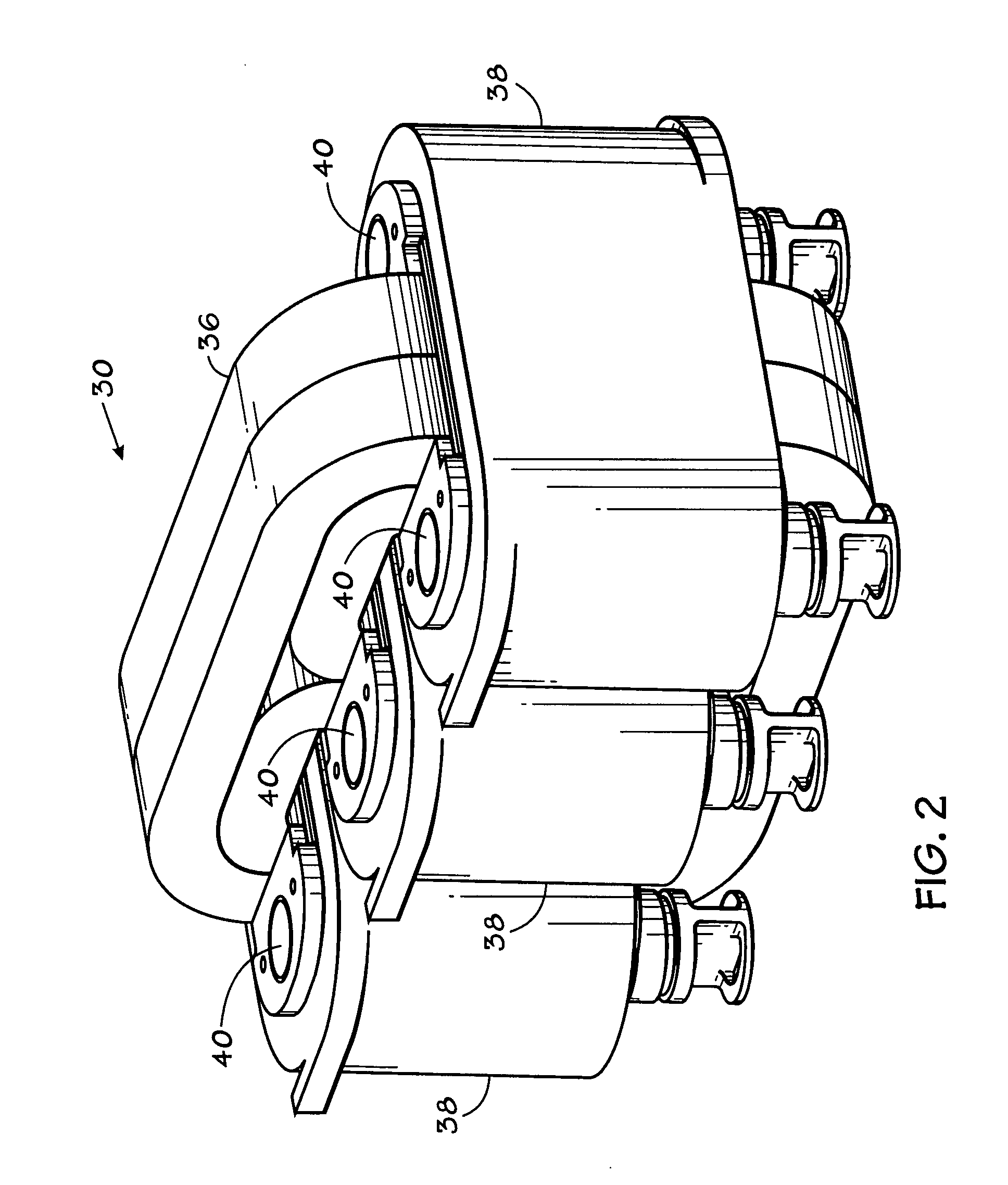
[0016]Various electronic circuits benefit from the use of inductors. Although inductors are useful for filtering, smoothing or otherwise conditioning power signals, inductors, including reactors, chokes, transformers, and the like, generally produce heat due to core and coil losses. Heat may degrade the performance of the inductor, or may cause degradation and premature failure of the device. Accordingly, the following embodiments provide a system and method to remove thermal energy from the core and the coils of an inductor. In certain embodiments, a cooling element is disposed adjacent to a core, such as between the core and the coil of an inductor such that it may absorb the heat generated by the inductor. In a presently contemplated embodiment, the core includes multiple core pieces that are urged outward by a biasing element disposed between the core pieces. Urging the core pieces outward promotes contact between the core pieces and a cooling element located proximate to the co...


PUM

PropertyMeasurementUnit
conductiveaaaaaaaaaa
resilientaaaaaaaaaa
coefficient of thermal expansionaaaaaaaaaa

Abstract

Provided is an electrical apparatus comprising a magnetic core, a conductive coil wound around at least a part of the core, a cooling element configured to receive a cooling fluid to cool the core and the coil during operation, and at least one biasing element operatively associated with the core to urge the core and the coil into engagement with the cooling element despite differential expansion or contraction of the core and the coil and manufacturing tolerances. Further provided is a method for making an electrical apparatus comprising disposing a conductive coil wound around at least a part of a magnetic core, disposing a cooling element between the core and the coil, the cooling element configured to receive a cooling fluid to cool the core and the coil during operation, and urging the core and the coil into engagement with the cooling element despite differential expansion or contraction of the core and the coil and manufacturing tolerances.

Description

BRIEF DESCRIPTION[0001]The present invention relates generally to the field of power electronic devices and their thermal management. More particularly, the invention relates to a technique for improving cooling and heat distribution in power modules.[0002]Power electronic devices and modules are used in a wide range of applications. For example, in electric motor controllers, rectifiers, inverters, and more generally, power converters are employed to condition incoming power and supply power to devices, such as a drive motor. However, the power and signals transmitted within the electronic devices often contain undesirable characteristics that may require additional devices to reduce or filter the signals. For instance, in alternating current (AC) motor controllers, a rectifier may be used to covert the AC power to stable direct current (DC) power, and an inverter may be used to convert the stable DC power back to the AC power supplied to the motor.[0003]In a standard three phase r...

Claims


Application Information

Patent Timeline
Patent Type & Authority Applications(United States)
IPC IPC(8): H01F27/10H01F17/04H01F41/00
CPCH01F27/10H01F27/22Y10T29/49073H01F37/00H01F27/266
Inventor AHANGAR, ABDOLMEHDI KAVEHKEEGAN, JEREMY J.
Owner ROCKWELL AUTOMATION TECH
Why Eureka
Try Eureka