
Noise resistant capacitive sensor

a capacitive sensor and resistance technology, applied in the field of electromechanical circuits, can solve the problems of low sensitivity of charge transfer methods to rf fields and rf noise, charge transfer techniques are still susceptible to rf noise, and charge transfer mechanisms are susceptible to noise having a frequency

Active Publication Date: 2009-01-01
CYPRESS SEMICON CORP
View PDF7 Cites 34 Cited by
  • Summary
  • Abstract
  • Description
  • Claims
  • Application Information

AI Technical Summary

Problems solved by technology

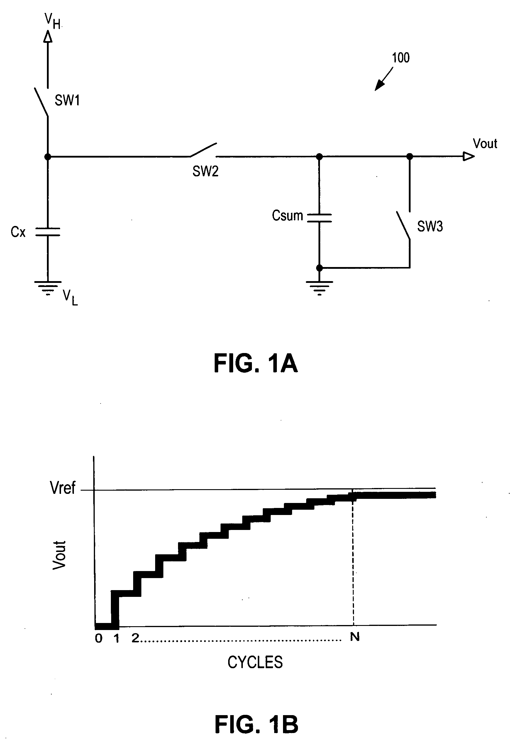
Relative to other capacitive sensing techniques, the charge transfer method has relatively low sensitivity to RF fields and RF noise.
However, the charge transfer technique is still susceptible to RF noise due to potential RF signal rectification by electrostatic discharge (“ESD”) protection circuits inside an integrated circuit (“IC”) implementation.
These DC current may arise from printed circuit board (“PCB”) or sensor assembly leakage problems, high power UHF signals (e.g., cell phones, microwave ovens, etc.), or rectification by on-chip electrostatic discharge (“ESD”) protection diodes.
Additionally, the charge transfer mechanism is susceptible to noise having a frequency matching (or harmonics thereof) the switching frequency of switches SW1 and SW2 due to an aliasing phenomenon.

Method used


Image

  • Noise resistant capacitive sensor
  • Noise resistant capacitive sensor
  • Noise resistant capacitive sensor

Examples


Embodiment Construction

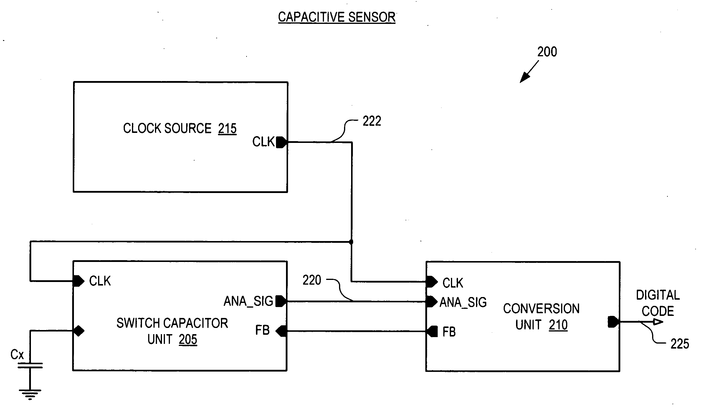
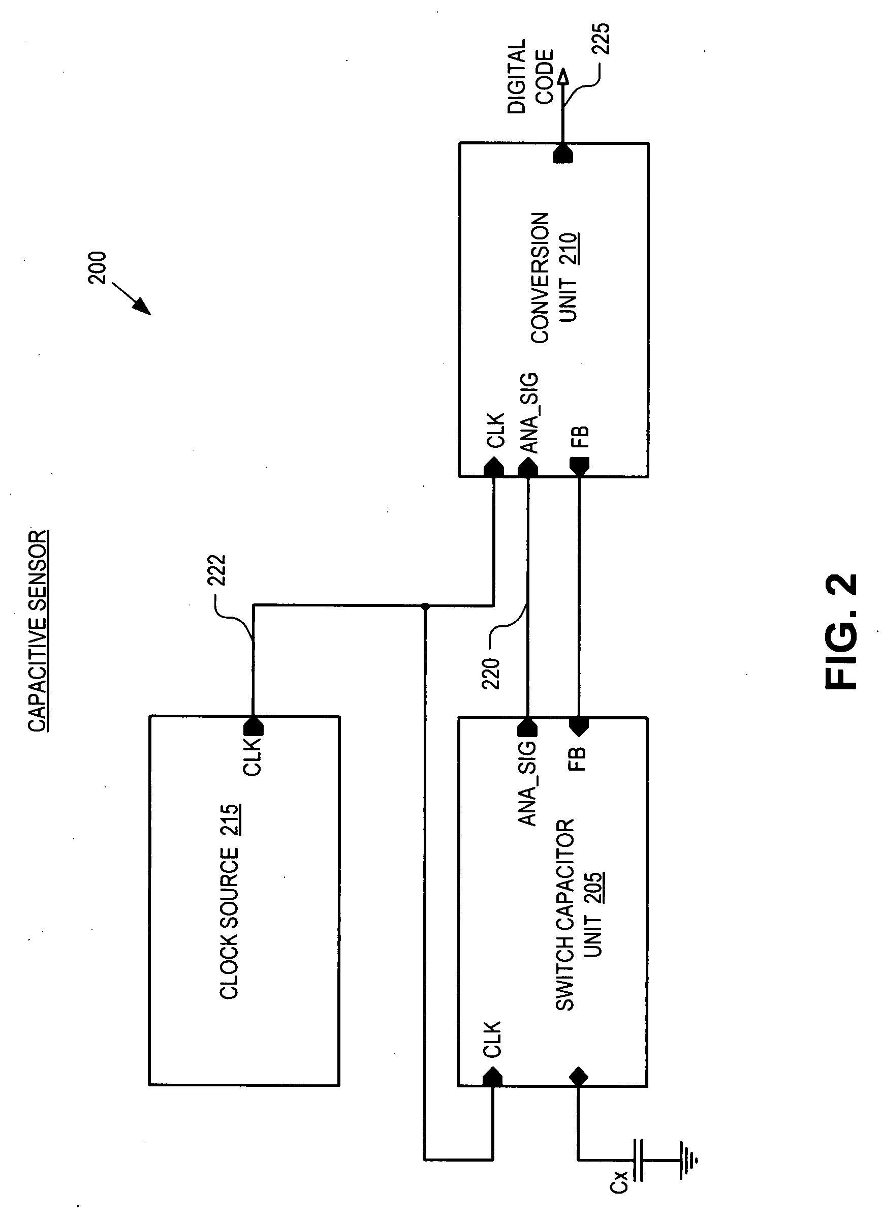
[0021]Embodiments of an apparatus and method for a noise resistant capacitive sensor are described herein. In the following description numerous specific details are set forth to provide a thorough understanding of the embodiments. One skilled in the relevant art will recognize, however, that the techniques described herein can be practice without one or more of the specific details, or with other methods, components, materials, etc. In other instances, well-known structures, materials, or operations are not shown or described in detail to avoid obscuring certain aspects.

[0022]Reference throughout this specification to “one embodiment” or “an embodiment” means that a particular feature, structure, or characteristic described in connection with the embodiment is included in at least one embodiment of the present invention. Thus, the appearances of the phrases “in one embodiment” or “in an embodiment” in various places throughout this specification are not necessarily all referring to...


PUM


Abstract

A switch capacitor unit for implementing a capacitive sensor includes a charging switch, a charge transfer switch, and a first switch. The charging switch is coupled between a first supply voltage and a circuit node to selectively couple a sensing capacitor to the first supply voltage through the circuit node. The charge transfer switch is coupled between the circuit node and a first terminal of a second capacitor to selectively couple the sensing capacitor through the circuit node to the second capacitor. The first switch is coupled between the circuit node and a second terminal of the second capacitor to selectively couple the second terminal to the sensing capacitor through the circuit node.

Description

TECHNICAL FIELD[0001]This disclosure relates generally to electronic circuits, and in particular but not exclusively, relates to capacitive sensor circuits.BACKGROUND INFORMATION[0002]Capacitance sensors are used to implement a variety of useful functions including touch sensors (e.g., touch pad, touch dial, touch wheel, etc.), determining the presence of an object, accelerometers, and other functions. In general, capacitive sensors are intended to replace mechanical buttons, knobs, and other similar mechanical user interface controls. A capacitive sensor permits eliminating complicated mechanical switches and buttons, providing reliable operation under harsh conditions. Capacitive sensors are widely used in the modern consumer applications, providing new user interface options in existing products (cell phones, digital music players, personal digital assistances, etc.).[0003]One class of capacitive sensor uses a charge transfer technique. Referring to FIG. 1, the charge transfer te...

Claims


Application Information

Patent Timeline
Patent Type & Authority Applications(United States)
IPC IPC(8): H03K17/96
CPCH03K17/16H03K2217/960725H03K17/962
Inventor KREMIN, VIKTOR
Owner CYPRESS SEMICON CORP
Learn More