Receiver aperture broadening for scanned beam imaging

Active Publication Date: 2009-01-01
MICROVISION +1
View PDF99 Cites 21 Cited by
  • Summary
  • Abstract
  • Description
  • Claims
  • Application Information

AI Technical Summary

Benefits of technology

[0011]In another aspect, the plurality of fibers may be a fiber bundle having an end surface configured to broaden the sensitivity or increase the numerical aperture of the fibers. According to an embodiment, the end surface may be coated with a diffusive material containing reflective particles that direct light to the end surfac

Problems solved by technology

This darkening may be associated both with lack of detection sensitivity a

Method used


Image

  • Receiver aperture broadening for scanned beam imaging
  • Receiver aperture broadening for scanned beam imaging
  • Receiver aperture broadening for scanned beam imaging

Examples


Embodiment Construction

[0036]Before describing the disclosed scanning beam assembly in detail, it should be noted that the disclosure is not limited in its application or use to the details of construction and arrangement of parts illustrated in the accompanying drawings and description. The illustrative embodiments may be implemented or incorporated in other embodiments, variations and modifications, and may be practiced or carried out in various ways. Furthermore, unless otherwise indicated, the terms and expressions employed herein have been chosen for the purpose of describing the illustrative embodiments for the convenience of the reader and are not intended to be limiting.

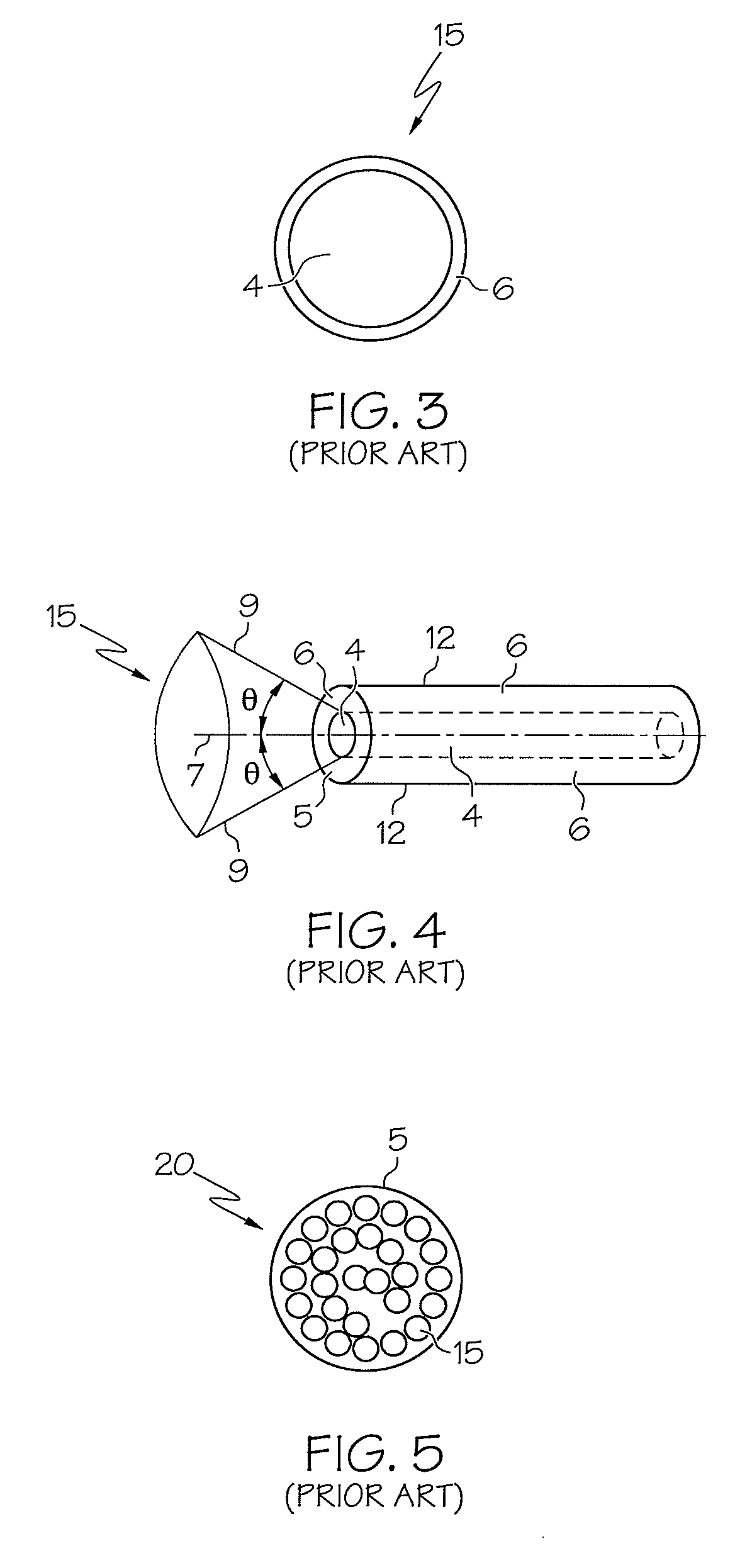
[0037]A step index optical fiber, generally designated 15 in FIG. 3, typically includes a core 4, and a cladding layer 6. The optical fiber 15 is a filament of transparent dielectric material that guides light using substantially total internal reflection. The core 4 is surrounded by, and is in intimate contact with, the cladding 6...


PUM


Abstract

A scanning beam assembly includes a beam generator to generate a beam of radiation; at least one reflector configured to deflect the beam across a field of view; and a plurality of multi-mode optical fibers for receiving radiation reflected from the field of view, wherein the optical fibers have end surfaces that face in at least two different directions, or wherein the optical fibers are configured to receive scattered radiation from an angular field of view larger than that determined by their individual numerical apertures.

Description

TECHNICAL FIELD [0001]The present disclosure is related generally to a scanned beam assembly adapted for imaging, and more particularly to a scanned beam assembly having light collectors with improved detection sensitivity at selected incident angles across a field of view.BACKGROUND OF THE INVENTION [0002]U.S. Published Application 2005 / 0020926A1, incorporated by reference herein, discloses a scanning beam imager which is reproduced in FIG. 1 herein. The imager may be used in applications in which cameras have been used in the past. In particular it may be used in medical devices such as video endoscopes, laparoscopes, etc.[0003]FIG. 1 shows a block diagram of one example of a scanned beam imager 102′. An illuminator 104′ creates a first beam of light 106′. A scanner 108′ deflects the first beam of light across a field-of-view (FOV) 111′ to produce a second scanned beam of light 110′, shown in two positions 110′a and 110′b. The illuminator 104′, first beam of light 106′ and scanner...

Claims


Application Information

Patent Timeline
IPC IPC(8): G02B26/08A61B6/00
CPCA61B1/00096A61B1/00167A61B1/0017A61B1/00172A61B1/00179A61B1/00181G02B6/04A61B1/0623A61B1/07A61B2562/0233A61B2562/028A61B2562/046A61B1/04B33Y80/00
Inventor WEIR, MICHAEL P.LEWIS, JOHN R.MALIK, AMJAD I.WIKLOF, CHRISTOPHER A.WATSON, MATHEW D.JAMES, RICHARD A.
Owner MICROVISION
Why Eureka
Try Eureka