

Zoom lens and imaging system using the same
a zoom lens and imaging system technology, applied in the field of zoom lens and imaging system, can solve the problems of inconvenient operation, the thickness of the optical system is the biggest bottleneck in reducing the depth dimension of the camera, and the use of the collapsible lens mount is not preferable in view of ease of operation, so as to prevent moisture and dust entry, easy to bend, and high optical performance
- Summary
- Abstract
- Description
- Claims
- Application Information
AI Technical Summary
Benefits of technology
Problems solved by technology
Method used
Image

Examples
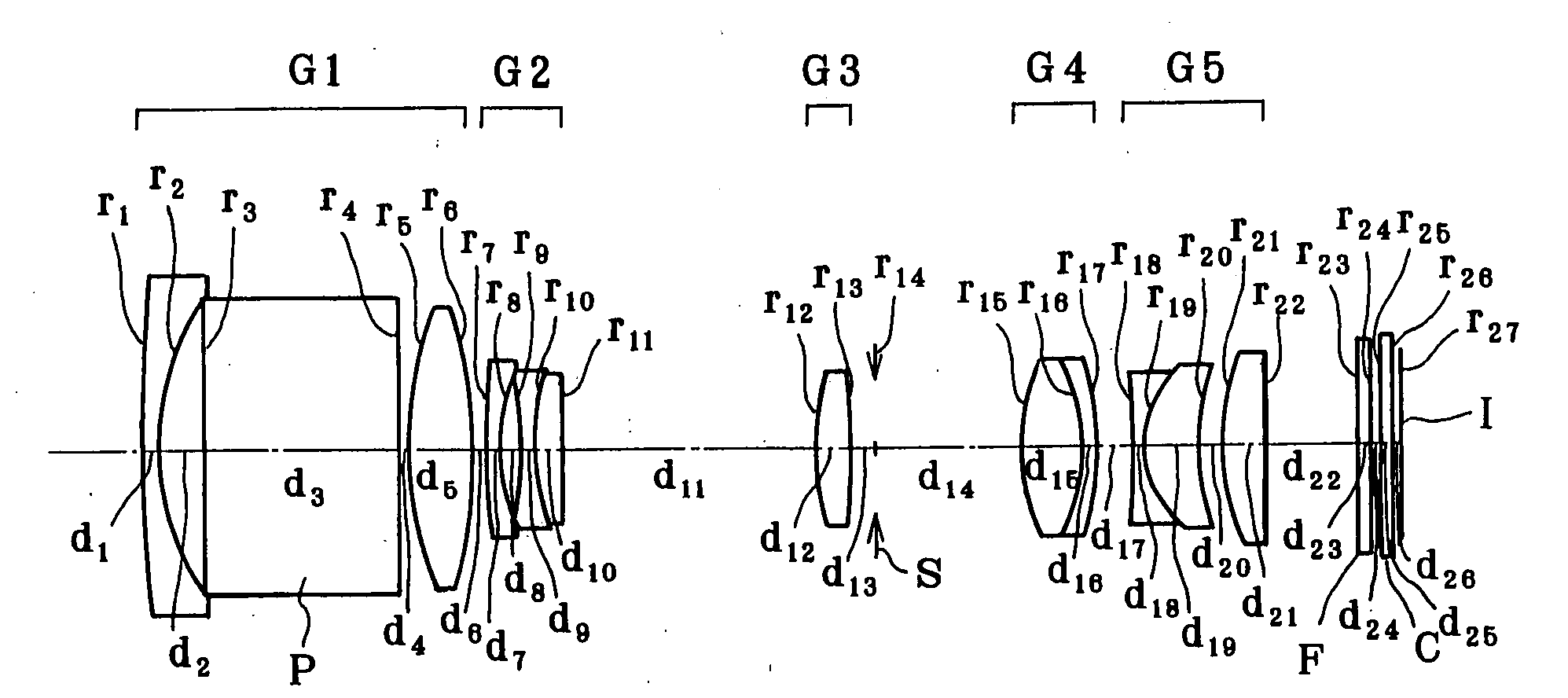
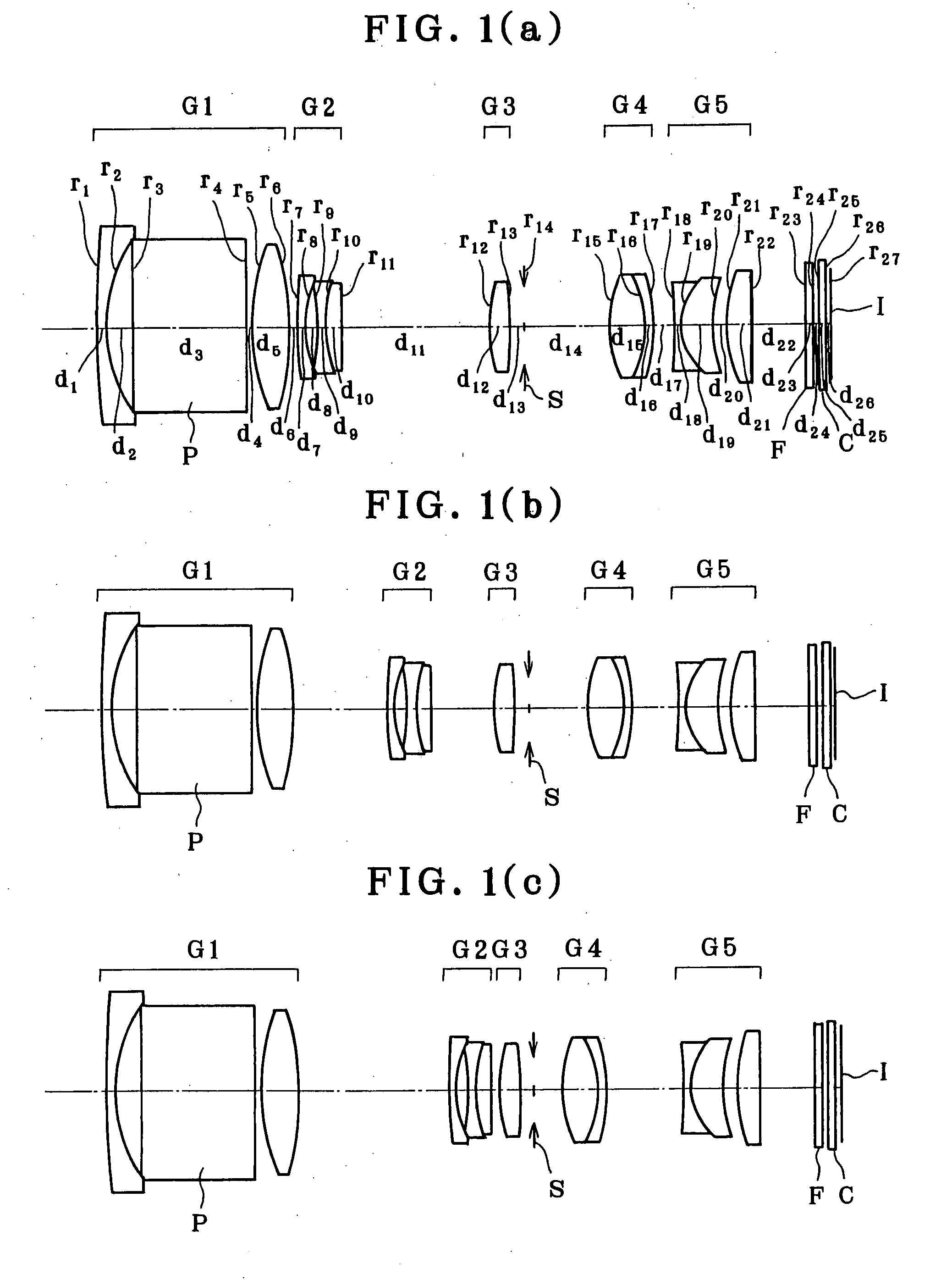
example 1
[0077]
r1 = 79.245d1 = 0.80nd1 = 2.00069νd1 = 25.46r2 = 10.737d2 = 1.85r3 = ∞d3 = 8.40nd2 = 2.00330νd2 = 28.27r4 = ∞d4 = 0.30r5 = 15.402 (Aspheric)d5 = 2.67nd3 = 1.76802νd3 = 49.24r6 = −22.552 (Aspheric)d6 = (Variable)r7 = 40.183d7 = 0.50nd4 = 1.88300νd4 = 40.76r8 = 7.191d8 = 1.07r9 = −14.386d9 = 0.45nd5 = 1.88300νd5 = 40.76r10 = 8.265d10 = 1.15nd6 = 1.92286νd6 = 20.88r11 = −8422.538d11 =(Variable)r12 = 9.608 (Aspheric)d12 = 1.54nd7 = 1.62299νd7 = 58.12r13 = −38.385 (Aspheric)d13 = 1.00r14 = ∞ (Stop)d14 =(Variable)r15 = 8.672 (Aspheric)d15 = 2.61nd8 = 1.62299νd8 = 58.12r16 = −6.739d16 = 0.54nd9 = 1.92286νd9 = 20.88r17 = −11.899d17 =(Variable)r18 = −44.226d18 = 0.50nd10 = 2.00330νd10 = 28.27r19 = 4.235d19 = 2.37nd11 = 1.51633νd11 = 64.14r20 = 9.498d20 = 0.94r21 = 10.761d21 = 1.80nd12 = 1.84666νd12 = 23.78r22 = −602.041d22 = 3.88r23 = ∞d23 = 0.50nd13 = 1.51680νd13 = 64.20r24 = ∞d24 = 0.50r25 = ∞d25 = 0.50nd14 = 1.51680νd14 = 64.20r26 = ∞d26 = 0.37r27 = ∞ (Imaging plane)Aspherical Coeff...
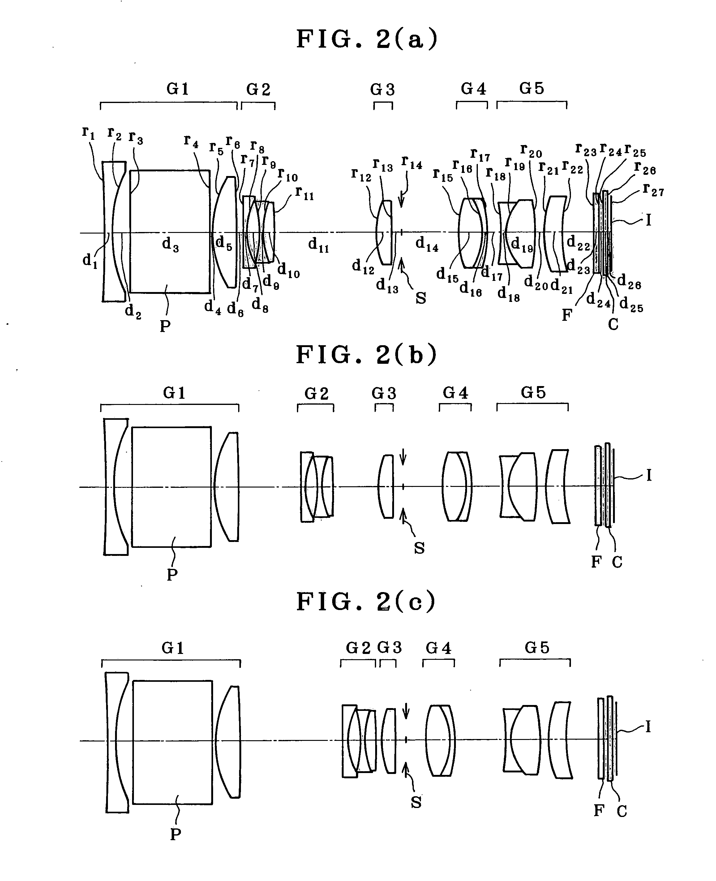
example 2
[0078]
r1 = −153.902d1 = 0.80nd1 = 2.00170νd1 = 20.60r2 = 12.979d2 = 1.91(Aspheric)r3 = ∞d3 = 8.50nd2 = 1.90366νd2 = 31.31r4 = ∞d4 = 0.30r5 = 10.604d5 = 2.58nd3 = 1.80139νd3 = 45.45(Aspheric)r6 = −74.045d6 = (Variable)(Aspheric)r7 = 180.770d7 = 0.50nd4 = 1.88300νd4 = 40.76r8 = 7.336d8 = 1.28r9 = −14.370d9 = 0.45nd5 = 1.88300νd5 = 40.76r10 = 8.729d10 = 1.15nd6 = 1.92286νd6 = 20.88r11 = −62.471d11 = (Variable)r12 = 8.946d12 = 1.54nd7 = 1.67790νd7 = 55.34(Aspheric)r13 = −116.820d13 = 1.00(Aspheric)r14 = ∞ (Stop)d14 = (Variable)r15 = 9.447d15 = 2.58nd8 = 1.62299νd8 = 58.12(Aspheric)r16 = −6.914d16 = 0.54nd9 = 1.92286νd9 = 20.88r17 = −12.280d17 = (Variable)r18 = −20.311d18 = 0.50nd10 = 2.00330νd10 = 28.27r19 = 5.042d19 = 3.10nd11 = 1.51633νd11 = 64.14r20 = −23.168d20 = 0.90r21 = 11.413d21 = 1.80nd12 = 1.84666νd12 = 23.78r22 = 14.325d22 = 3.32r23 = ∞d23 = 0.50nd13 = 1.51680νd13 = 64.20r24 = ∞d24 = 0.50r25 = ∞d25 = 0.50nd14 = 1.51680νd14 = 64.20r26 = ∞d26 = 0.37r27 = ∞(Imagingplane)Aspheric...
example 3
[0079]
r1 = 94.193d1 = 0.80nd1 = 2.00069νd1 = 25.46r2 = 10.777d2 = 1.90r3 = ∞d3 = 8.40nd2 = 2.00330νd2 = 28.27r4 = ∞d4 = 0.30r5 = 15.253d5 = 2.67nd3 = 1.76802νd3 = 49.24(Aspheric)r6 = −22.635d6 = (Variable)(Aspheric)r7 = 30.598d7 = 0.50nd4 = 1.88300νd4 = 40.76r8 = 7.008d8 = 1.08r9 = −14.944d9 = 0.45nd5 = 1.88300νd5 = 40.76r10 = 7.893d10 = 1.12nd6 = 1.92286νd6 = 20.88r11 = 162.059d11 = (Variable)r12 = 9.600d12 = 1.54nd7 = 1.62299νd7 = 58.12(Aspheric)r13 = −37.829d13 = 1.00(Aspheric)r14 = ∞ (Stop)d14 = (Variable)r15 = 8.474d15 = 2.66nd8 = 1.62299νd8 = 58.12(Aspheric)r16 = −6.619d16 = 0.54nd9 = 1.92286νd9 = 20.88r17 = −11.728d17 = (Variable)r18 = −29.689d18 = 0.50nd10 = 2.00330νd10 = 28.27r19 = 4.379d19 = 2.19nd11 = 1.51633νd11 = 64.14r20 = 10.038d20 = 0.97r21 = 12.327d21 = 1.80nd12 = 1.84666νd12 = 23.78r22 = −68.566d22 = 4.01r23 = ∞d23 = 0.50nd13 = 1.51680νd13 = 64.20r24 = ∞d24 = 0.50r25 = ∞d25 = 0.50nd14 = 1.51680νd14 = 64.20r26 = ∞d26 = 0.37r27 = ∞(Imagingplane)Aspherical Coefficient...
PUM
 Abstract
Description
Claims
Application Information