Power Converter

a power converter and converter technology, applied in the direction of engine-driven generators, electric devices, transportation and packaging, etc., can solve problems such as confirmation of positioning, and achieve the effects of reducing the production cost and increasing the productivity of the power converter

Active Publication Date: 2009-01-01
HITACHI ASTEMO LTD
View PDF37 Cites 83 Cited by
  • Summary
  • Abstract
  • Description
  • Claims
  • Application Information

AI Technical Summary

Benefits of technology

[0013]In the typical aspect of the present invention, since an assembling efficiency is increased over the prior art, there can be provided a power converter which is suitably increased in productivity.
[0014]The increased productivity of the power converter enables the production cost of the power converter to be lowered and a system having the power converter mounted therein to be inexpensively manufactured. For example, when the power converter is mounted to an environmental friendly vehicle such as a hybrid car, the price of the hybrid car can be lowered, thus contributing to spread of the environmental friendly vehicle.

Problems solved by technology

In such a case, it is hard to secure a sufficient working zone in the vicinity of the plurality of electrodes or terminals provided to the power module, it becomes highly difficult to confirm the positioning to the plate-shaped conductors (bus bars) and thus the interconnecting works between the plurality of electrodes or terminals provided to the power module and the plate-shaped conductors (bus bars).

Method used


Image

  • Power Converter
  • Power Converter
  • Power Converter

Examples


embodiment 1

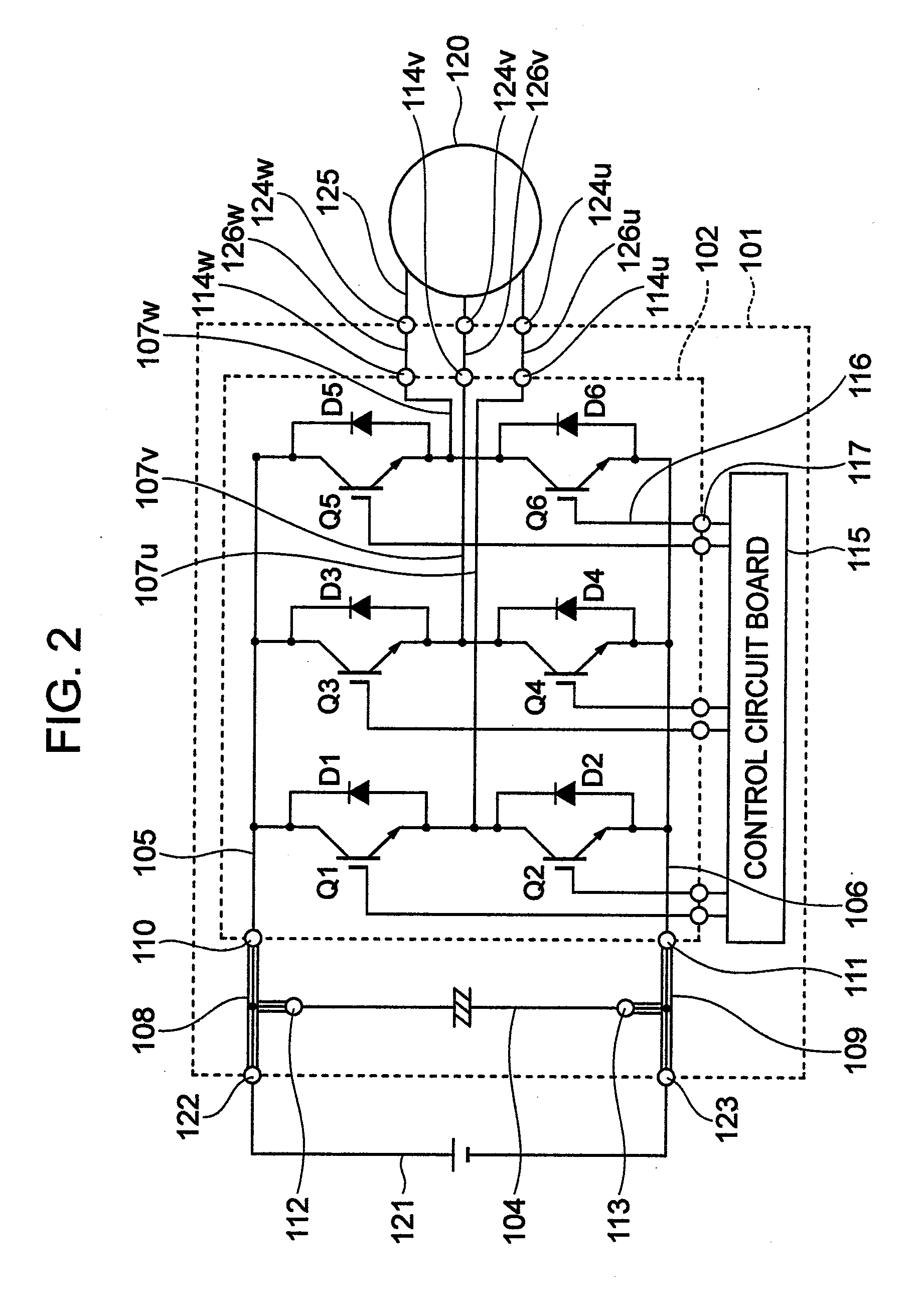
[0054]FIG. 2 shows a circuit diagram of a power converter in accordance with an embodiment of the present invention, showing a DC power source 121, a rotary electric machine 120, and a power converter 101, connected to the circuit diagram.

[0055]In FIG. 2, the interior of the power converter 101 is shown by a dotted line frame, and the frame corresponds to a casing (denoted by reference numeral 901 in FIG. 11) of the power converter 101.

[0056]Provided in the interior of the power converter 101 are a smoothing capacitor 104, a power module 102, and a control circuit board 115. A dotted line frame indicative of the power module 102 corresponds to a case (denoted by reference numeral 201, 202 in FIG. 1) of the power module 102.

[0057]The DC power source 121 is located outside of the power converter 101 and a plus terminal of the DC power source 121 is connected to one end of the smoothing capacitor 104 via a connection 122 of the power converter 101 and also connected to a plus side line...

embodiment 2

[0103]FIGS. 7A and 7B show arrangements of a power converter in accordance with another embodiment of the present invention. FIG. 7A is a perspective view of the power module 102 built in the power converter, and FIG. 7B is a perspective view of the power module 102, showing the power module 102 and interconnections between the DC bus bars 108, 109 and the AC conductor 126u, 126v, 126w when the power module 102 is built in the power converter. FIG. 8 shows a cross-sectional view of the power converter taken along a line VIII-VIII in FIG. 7B.

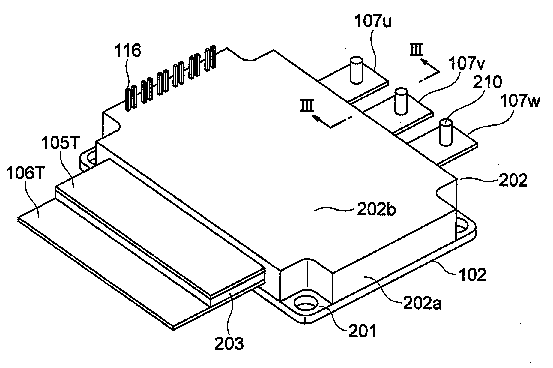
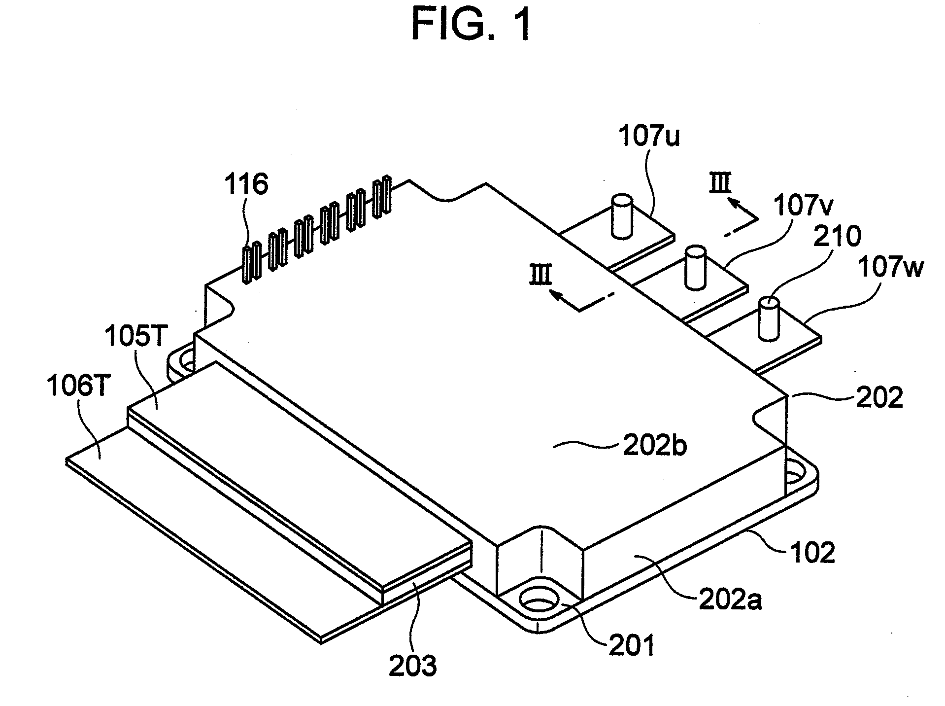
[0104]FIG. 7A corresponds to FIG. 1, and is different from FIG. 1 in that a male screw 601A is embedded in the plus-side main electrode 105T to be projected upwards in the drawing and a male screw 601B is embedded in the minus-side main electrode 106T to be projected upwards in the drawing.

[0105]As in the case of FIG. 1, the male screw 210 is embedded in each of the AC-side main electrodes 107u, 107v and 107w.

[0106]The DC bus bars 108 and 109 co...

embodiment 3

[0115]FIGS. 10A and 10B show arrangements of a power converter in accordance with another embodiment.

[0116]FIG. 10A is a perspective view of the power module 102 when built in the power converter, and FIG. 10B is a perspective view of the power module 102 when built in the power converter, showing a connection arrangement among the power module 102, the DC bus bars 108, and the AC conductors 126u, 126v, 126w.

[0117]FIGS. 10A and 10B correspond to FIGS. 7A and 7B, and are different from FIGS. 7A and 7B by the plus-side main electrode 105T and the minus-side main electrode 106T.

[0118]That is, as shown in FIG. 10A, the plus-side main electrode 105T is arranged not to be overlapped with the minus-side main electrode 106T but to be parallel to each other in a plane parallel to the base 201.

[0119]The above electrode arrangement holds true even for the AC-side main electrodes 107u, 107v, 107w.

[0120]The male screw 601A is embedded in the plus-side main electrode 105T to be projected upward...


PUM


Abstract

A power converter which can attain a reliable electric connection with electrodes of a power module by facilitating positioning of conductors connected to the electrodes of the power module. The power converter includes the power module having the plurality of electrodes in the form of plate-shaped conductors within a casing having a lid, and also includes a plurality of plate-shaped conductors connected to the electrodes of the power module. Male screws are embedded in ones of the electrodes of the power module provided at least on the side of the lid to be projected therefrom, the plate-shaped conductors connected to the electrodes having the male screws are formed therein with holes at locations corresponding to the male screws, the male screws being inserted in the corresponding holes, and electrically connected with the electrodes with nuts fastened to the male screws.

Description

BACKGROUND OF THE INVENTION[0001]The present invention relates to a power converter and more particularly, to a technique for increasing the productivity of the power converter.[0002]A power converter, for example, an inverter includes, as its main constituent elements, a power module having a plurality of switching semiconductor elements, a control circuit board for controlling the operations of the plurality of switching semiconductor elements in the power module, and a smoothing capacitor connected to a DC side of the power module. Respective constituent elements including the aforementioned elements are accommodated within a single casing.[0003]The inverter thus arranged is located between a DC power source and an electrical load so that a DC power source side of the inverter is connected to both ends of the smoothing capacitor and an electrical load side of the inverter is connected to an AC side of the power module. In the inverter, a signal indicative of a torque command or a...

Claims


Application Information

Patent Timeline
Patent Type & Authority Applications(United States)
IPC IPC(8): H05K7/10B60L50/16
CPCB60L1/003Y02T10/70B60L7/14B60L11/14B60L2210/14B60L2220/14B60L2240/12B60L2240/36B60L2240/421B60L2240/423B60L2240/441B60L2240/443B60L2240/461B60L2240/463B60L2240/465B60L2260/28H01R4/30H01R9/2425H01R2201/26H02M7/003H05K7/1432Y02T10/642Y02T10/7077Y02T10/7225H01L2924/0002B60L3/106H01L2924/00B60L50/16Y02T10/64Y02T10/72Y02T10/7072H05K7/14329
Inventor SUWA, TOKIHITOKUNII, KEIJISHIMIZU, HISAYA
Owner HITACHI ASTEMO LTD
Why Eureka
Try Eureka