Planar Illumination Light Source Device and Planar Illumination Light Device Using The Planar Illumination Light Source Device

a light source device and light source technology, applied in the direction of identification means, lighting and heating apparatus, instruments, etc., can solve the problems of large space, inability to obtain uniform illumination light, and inability to fully utilize the light emitted from an led

Inactive Publication Date: 2009-01-01
OPTO DESIGN INC
View PDF8 Cites 176 Cited by
  • Summary
  • Abstract
  • Description
  • Claims
  • Application Information

AI Technical Summary

Benefits of technology

[0098]According to the present invention, the amount of light on the front plane of the highly directional light source and the light amount limited on the front plane are compensated by the light reflected in the light guiding body; accordingly, illumination light that is entirely uniformized can be obtained. Also, by arranging a plurality of the planar illumination light source devices, a planar illumination light device that emits even illumination light can be configured.

Problems solved by technology

Accordingly, a large space is required.
Also, the light emitted from an LED is not intended to be utilized entirely.
Accordingly, it is not possible to obtain uniform illumination light while the light emitted from the LED is utilized entirely in a space surrounding the LED.

Method used


Image

  • Planar Illumination Light Source Device and Planar Illumination Light Device Using The Planar Illumination Light Source Device
  • Planar Illumination Light Source Device and Planar Illumination Light Device Using The Planar Illumination Light Source Device
  • Planar Illumination Light Source Device and Planar Illumination Light Device Using The Planar Illumination Light Source Device

Examples


third embodiment

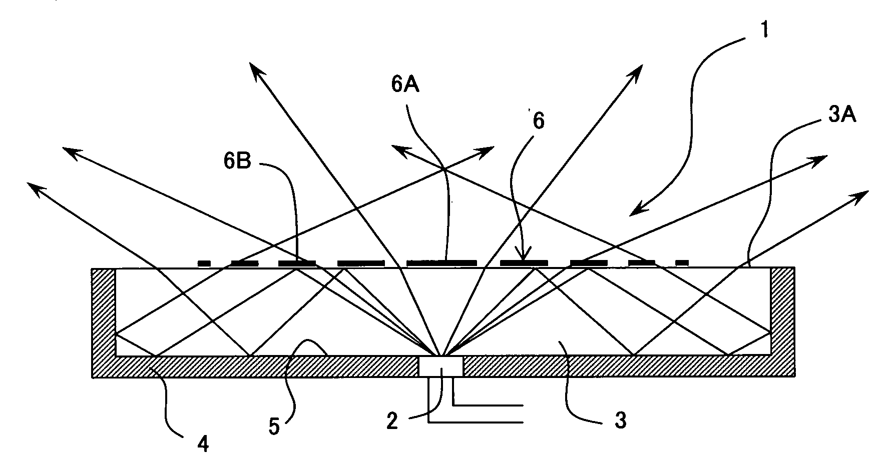
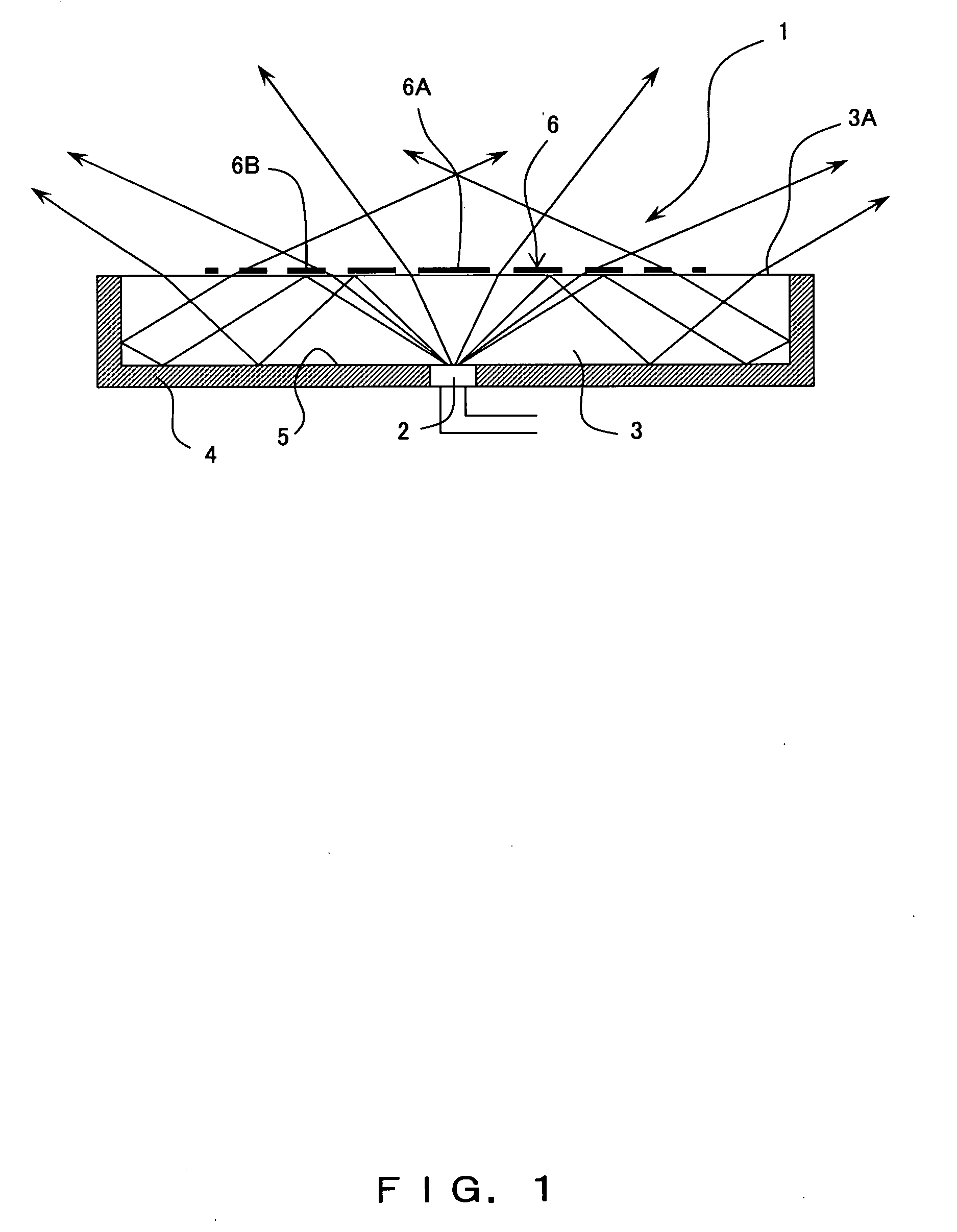
[0200]FIGS. 4A and 4B show the radiation side reflection part 6 according to the present embodiment.

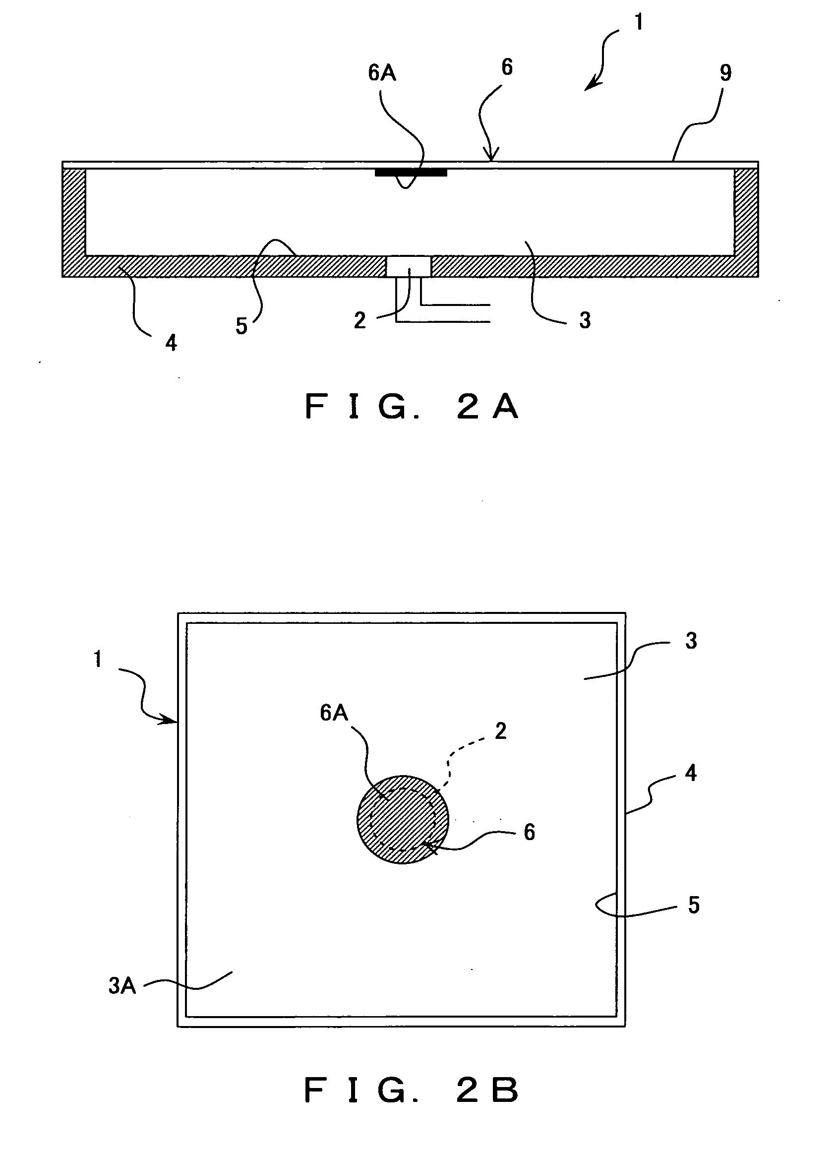
[0201]As shown in FIG. 4A, the radiation side reflection part 6 has a rectangle-shaped central reflection part 6A formed to be similar to the casing 4 provided to the light guiding body 3, and a plurality of looped outward reflection parts 6B arranged around the central reflection part 6A outwardly at a prescribed interval. Thereby, the outward light transmissive parts 7 are formed at a prescribed interval.

[0202]Further, the central reflection part 6A is a reflection plate or reflection film formed, on the radiation plane 3A, to be similar to the casing 4. The outward reflection parts 6B are a belt-shaped reflection plate or reflection film formed on the reflection plate or reflection film at a prescribed interval.

[0203]Thereby, it is possible to limit the amount of the transmitted light at the center portion having a great amount of light and to increase the amount of the transmitted...

fourth embodiment

[0205]FIG. 5 shows the radiation side reflection part 6 according to the present embodiment.

[0206]In the present embodiment, the radiation side reflection part 6 is a conical reflection body 8 having a prescribed vertical angle provided on the radiation plane 3A in front of the light source 2. This reflection body 8 is desirably a cone that can uniformly reflect light or a pyramid-shaped body similar to the casing. Also, by setting the vertical angel thereof, it is possible to reflect all or a part of the light emitted from the light source substantially directly to the radiation plane. Thereby, it is possible to attain the same effect as that of the first embodiment.

fifth embodiment

[0207]FIG. 6 shows the radiation side reflection part 6 according to the present embodiment.

[0208]In the present embodiment, radiation side reflection parts 10 are formed on reflection dots made of a reflecting material. These radiation side reflection parts 10 consist of a central side reflection part 10A consisting of reflection dots of a high density distribution, and an outward reflection part 10B consisting of reflection dots of a density distribution lower than that of the central side reflection part 10A. Thereby, it is possible to attain the same effect as that of the first embodiment.


PUM


Abstract

The present invention provides a planar illumination light source device by which uniform illumination light can be obtained over a wide area without increasing the thickness of LEDs in the radiation direction even when a highly directional light source such as LEDs is used, and a planar illumination device using this. The present invention includes a highly directional light source, a light guiding body having a radiation plane in a radiation direction of the light source, a casing that encloses the light source and seals planes other than the radiation plane of the light guiding body, inside reflection means provided in the entirety of the area between the casing and the light guiding body, and radiation side reflection means provided on the radiation plane and reflecting light from the light source at a prescribed ratio. A light emitting diode group consisting of one or a plurality of light emitting diodes is used as the highly directional light source.

Description

TECHNICAL FIELD[0001]The present invention relates to a planar illumination light source device used for LCD back light devices, illumination boards, display devices such as those for automobiles, vehicles, or the like, and also to a planar illumination light device using the planar illumination light source device.BACKGROUND ART[0002]A planar illumination light source device according to Patent Document 1 includes at least one primary light source and a plate-shaped light guiding body that guides the light emitted from the primary light source and that has a light-incident-end face on which the light emitted from the primary light source is incident and a light emission plane for emitting light to be guided; the light guiding body has a light emission mechanism on at least one of the light emission faces and the back face thereof, and also has at least one local lens array formation part on at least one of the light emission faces and the back face thereof, each of the local lens a...

Claims


Application Information

Patent Timeline
Patent Type & Authority Applications(United States)
IPC IPC(8): F21V7/00
CPCF21Y2105/00G02B6/0043G02B6/0055G02B6/0061G09F13/22G02F1/133605G02F1/133611G09F3/0297G02F1/133603F21V7/04F21Y2115/10
Inventor SATO, EIICHI
Owner OPTO DESIGN INC
Why Eureka
Try Eureka