Method for fabricating photomask

a technology of photomasks and fabrication methods, applied in the field of photomask fabrication methods, can solve the problems of defective patterns and the need for photomasks to fall into disuse, and achieve the effect of improving the fabrication yield of photomasks

Inactive Publication Date: 2009-01-01
SK HYNIX INC
View PDF6 Cites 5 Cited by
  • Summary
  • Abstract
  • Description
  • Claims
  • Application Information

AI Technical Summary

Benefits of technology

[0007]Embodiments of the present invention are directed to a method for fabricating a photomask that can improve a fabrication yield of a photomask by preventing contaminants from adhering and accumulating onto a mask surface.

Problems solved by technology

Therefore, the particles are formed around fine patterns formed on the mask or on the quartz (Qz) substrate to thereby cause defective patterns.
In some cases, it is so serious that the photomask must fall into disuse.

Method used


Image

  • Method for fabricating photomask
  • Method for fabricating photomask
  • Method for fabricating photomask

Examples


Embodiment Construction

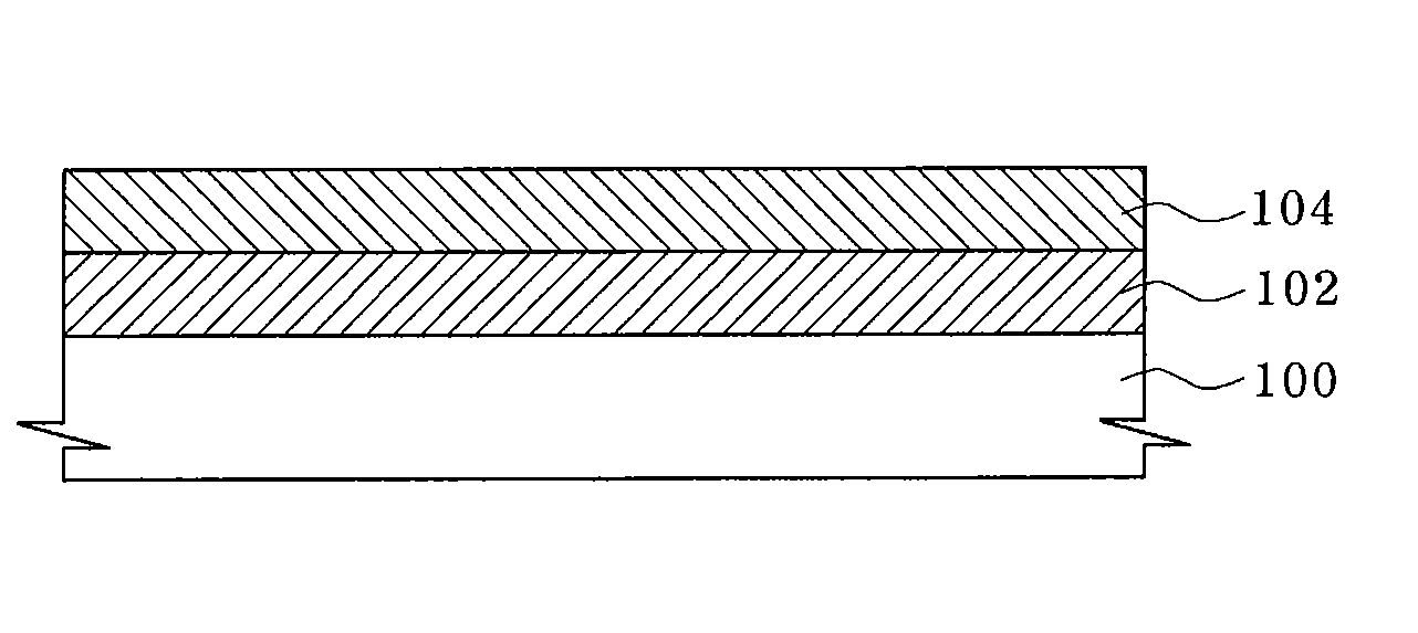
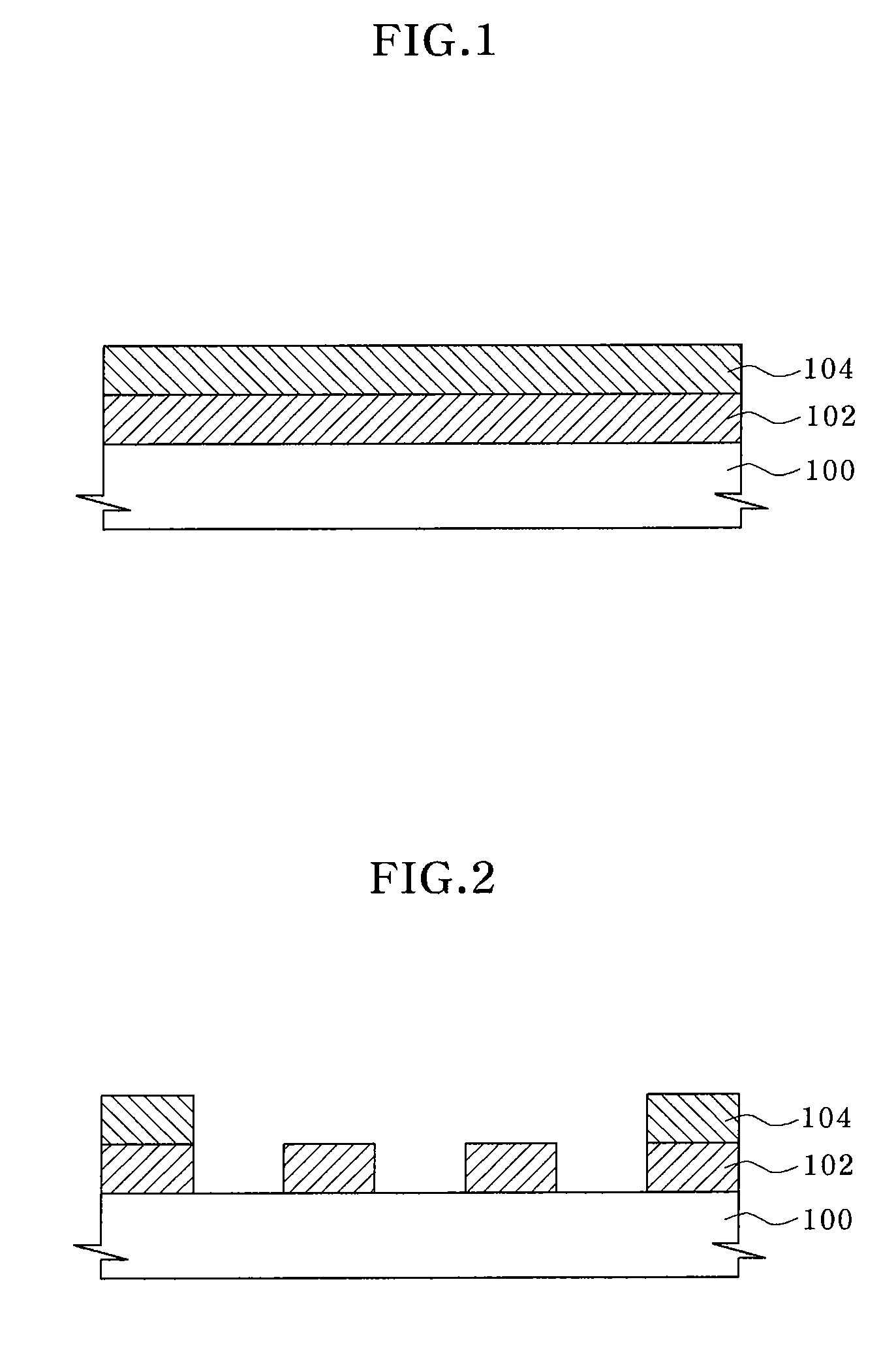
[0014]Generally, in a semiconductor device fabrication environment, moisture of approximately 45% is present in a process chamber. In a photomask storage environment, a mask substrate or a phase shift layer contacts and reacts with sulfur dioxide (SO2) and ammonia (NH3). Hence, contaminants are generated on the mask substrate or the phase shift layer due to such reaction and an influence of the moisture. Nuclei of the contaminants are formed of ammonium sulfate ((NH4)2SO4), and water molecules are held to the nuclei of the contaminants to gradually increase the size of contaminant particles.

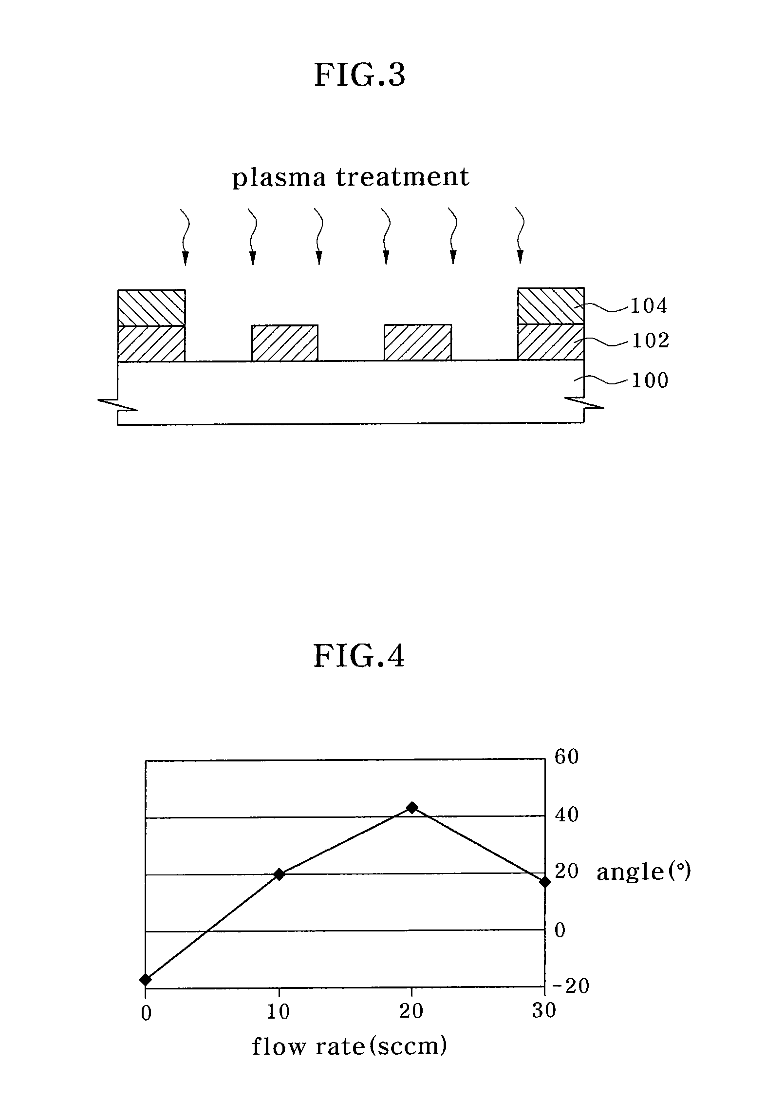
[0015]In order to suppress the growth of the ammonium sulfate ((NH4)2SO4), adsorption of the moisture on the mask substrate is blocked. Surface properties of the mask substrate become hydrophobic in order to block the adsorption of the moisture. As one example, the surface of the mask substrate is treated using plasma gas.

[0016]FIGS. 1 to 3 illustrate a method for fabricating a photomask accordin...


PUM

PropertyMeasurementUnit
pressureaaaaaaaaaa
surface propertyaaaaaaaaaa
hydrophobicityaaaaaaaaaa

Abstract

Provided is a method for fabricating a photomask. The method includes following processes. Light blocking patterns are formed on a mask substrate, and surface properties of the mask substrate on which the light blocking patterns are formed are changed into hydrophobicity. When the surface properties of the mask substrate are changed into the hydrophobicity, the mask substrate is treated using plasma gas. The plasma gas may be a gas mixture of trifluoromethane (CHF3), tetrafluoromethane (CF4), and hydrogen (H2).

Description

CROSS-REFERENCE TO RELATED APPLICATIONS[0001]The present application claims priority to Korean patent application number 10-2007-0063942, filed on Jun. 27, 2007, which is incorporated by reference in its entirety.BACKGROUND OF THE INVENTION[0002]The present invention relates to a method for fabricating a photomask, and more particularly, to a method for fabricating a photomask including a phase shift layer.[0003]Various patterns in semiconductor devices are formed by photolithography. Recently, as semiconductor devices become highly integrated, various technologies for forming ultra-fine patterns are developing. In order to improve the resolution by using a mask pattern, patterns are formed using a phase shift mask including a phase shifter.[0004]The phase shift mask increases resolution or depth of focus by using interference or partial interference of light to expose patterns having a desired size. That is, when light passes through a mask substrate, a phase difference of the ligh...

Claims


Application Information

Patent Timeline
Patent Type & Authority Applications(United States)
IPC IPC(8): G03F1/00
CPCG03F1/26G03F1/68G03F1/54G03F1/38H01L21/0274H01L21/0337
Inventor LEE, JUN SIK
Owner SK HYNIX INC
Why Eureka
Try Eureka