Tissue treatment apparatus

a technology of tissue treatment and treatment apparatus, which is applied in the field of tissue treatment apparatus, can solve the problems of increasing the energy of the pulse, the tissue onto which the plasma is being directed, and the increase of the applied pulse duration

Inactive Publication Date: 2009-01-01
ENERGIST
View PDF8 Cites 11 Cited by
  • Summary
  • Abstract
  • Description
  • Claims
  • Application Information

AI Technical Summary

Benefits of technology

[0018]According to another aspect of the present invention, there is provided a method of controlling a tissue treatment system having an r.f. generator, a treatment instrument, and an optical analysis device, the instrument being connectible to the generator and to a source of ionisable gas and operable to produce a plasma jet at a nozzle of the instrument when supplied with the ionisable gas and energised by the generator. The method comprises the steps of supplying ionisable gas from the gas conduit; actuating the generator to apply a radio frequency (RF) voltage to a pair of electrodes associated with the conduit to produce an electric field in the conduit and thereby to produce a plasma in the ionisable gas flowing through the conduit; receiving, in at least one optical detector, radiation emitted by the plasma, the radiation being received directly from within the conduit; comparing a representation of signals outputted from the at least one optical detector with a reference representation; generating a fault signal in response to a predetermined comparison result the fault signal being indicative of a fault in the tissue treatment apparatus; and controlling the generation of r.f. energy by the generator in response to the fault signal.

Problems solved by technology

If the system was to malfunction, causing, for example, the duration of the applied pulse to increase substantially, or causing the energy of the pulse to increase substantially, the tissue onto which the plasma is being directed may be irreparably damaged.
Likewise, if the system were to malfunction causing the duration of the applied pulse to be significantly shorter or causing the energy of the pulse to decrease substantially then the tissue onto which the plasma is being directed may not be treated adequately for the intended purpose.
The circulator and directional coupler described above are both relatively expensive, and reflections occurring other than those associated with the generation of plasma at the handpiece can compromise performance.
Such multiple reflections cannot readily be analysed, and hence they cannot be distinguished from the reflected r.f. power signal.
Additionally, the reflected r.f. power signal is not a true indicator of satisfactory plasma generation.

Method used


Image

  • Tissue treatment apparatus
  • Tissue treatment apparatus
  • Tissue treatment apparatus

Examples


first embodiment

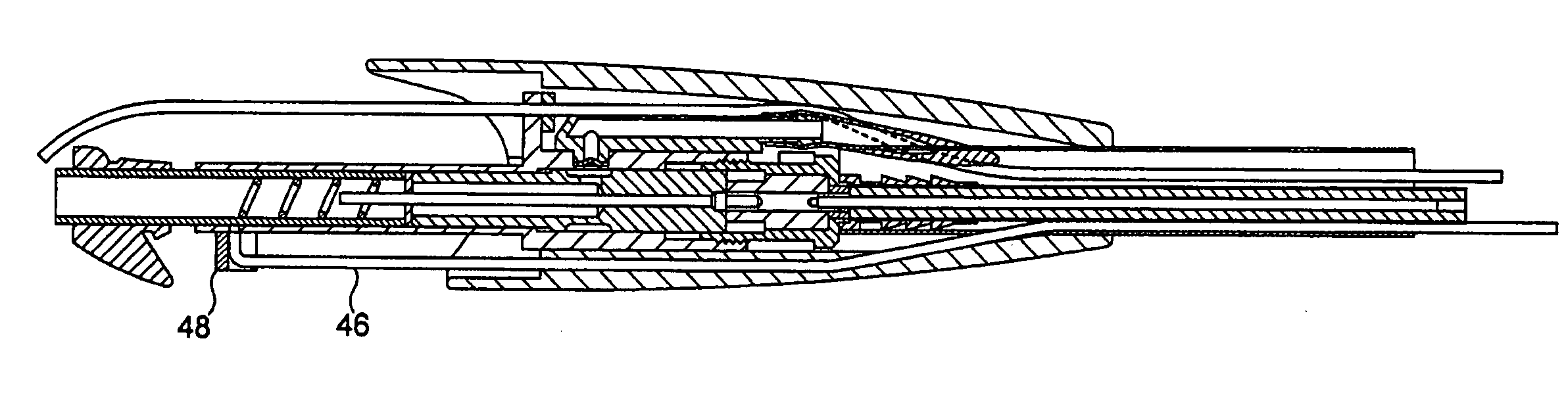
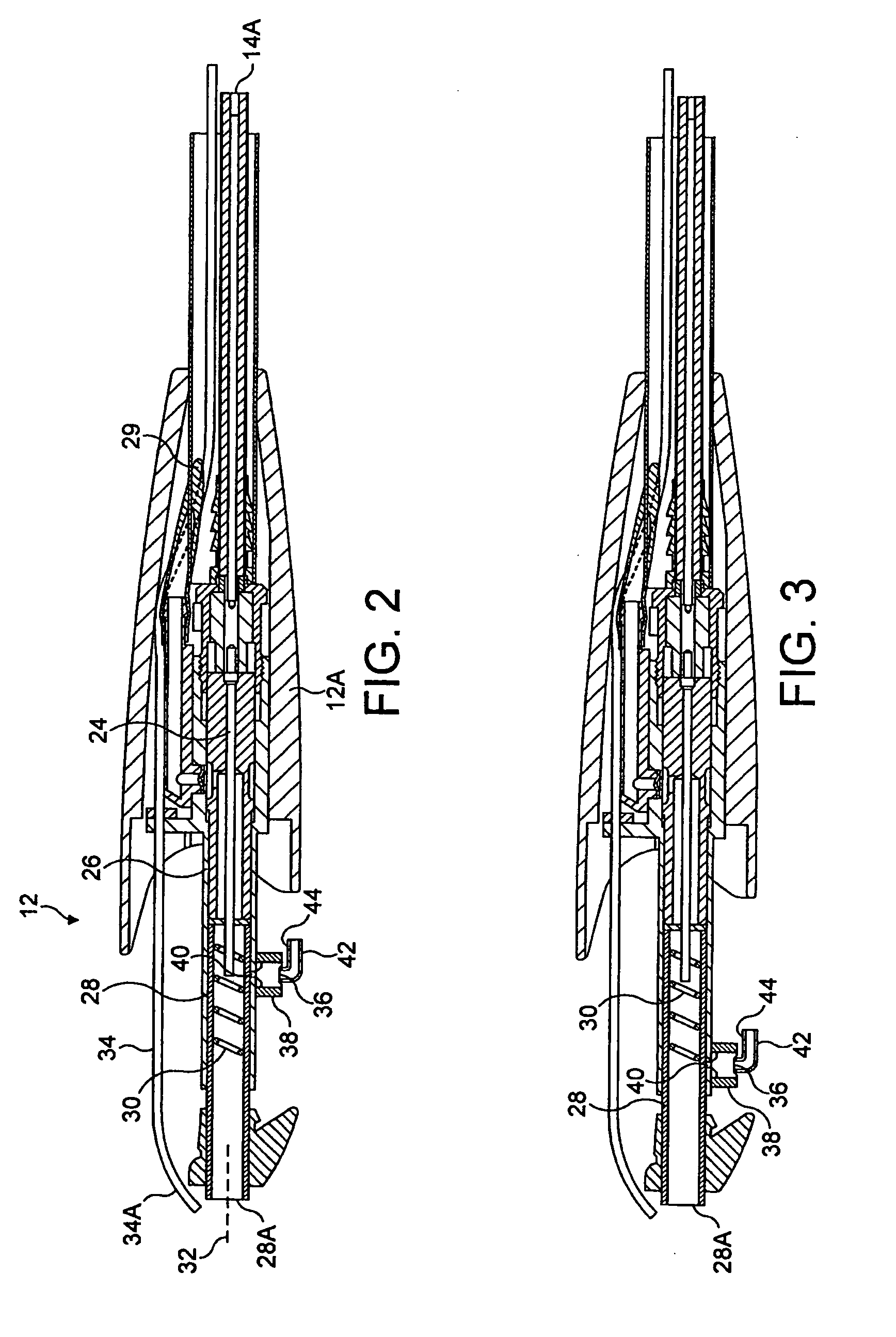
[0039]In this first embodiment of the invention, an optical detector 36 is removably attached to an outer surface of the outer electrode 26 by means of a mounting member 38. The optical detector 36 is positioned such that it receives radiation from within the quartz tube 28 through a small aperture 40 in the surface of the outer electrode 26. The optical detector 36 is connected (a) to a power cable 42, the other end of which is connected to a power supply (not shown) to provide power to the optical detector, and (b) to a signal cable 44, the other end of which is connected to a central processing unit (CPU) (not shown) contained within the base unit 10. Any suitable optical detector 36 may be used, for example an integrated photo-optics sensor (model IPL 10530 DAL) made by Integrated Photo-Optics Limited. The aperture 40 is configured such that only a minimum amount of r.f. energy is leaked from within the quartz tube 28 whilst permitting adequate optical energy to reach the detect...

second embodiment

[0041]In the invention, as illustrated in FIG. 3, the optical detector 36 is removably connected, as before, to the surface of the outer electrode 26 by means of a mounting member 38, but is positioned at a distal end of the resonant coil 30. Radiation emitted from within the resonant coil 30 passes through a small aperture 40 and is detected by the optical detector 36, the output of which is fed to the CPU via signal cable 44. In this embodiment, the optical detector 36 views plasma that is forming and flowing within the resonant coil 30 and from the distal end of the inner electrode, before it reaches the exist nozzle 28A of the quartz tube 28.

third embodiment

[0042]In the present invention, as illustrated by FIG. 4, the optical detector 36 is removably connected to the exit nozzle 28A end of the quartz tube 28 by means of a mounting member 38. Since, in this embodiment, the optical detector 36 is positioned beyond the distal end of the outer conductor 26 and is attached directly to the quartz tube 28, which is substantially transparent, no aperture is required. As the plasma that is generated within the resonant coil 30 flows through the quartz tube 28, the quartz becomes hot. It is preferable, therefore, that the optical detector 36 is spaced from the surface of the quartz by means of a spacer (not shown), to avoid overheating, and possibly damaging, the optical detector.

[0043]In this embodiment, with the optical detector 36 positioned at the distal end of the quartz tube 28, the plasma radiation that is detected is substantially from the Lewis-Rayleigh afterglow. The quartz tube 28, and hence the mounting member 38, form part of the di...


PUM


Abstract

In tissue treatment apparatus for skin resurfacing having a handheld treatment instrument with electrodes connected to a radio frequency generator, a plasma jet is produced by ionising gas passing through a gas conduit in the instrument, the plasma emerging from a nozzle at an end of the conduit. Incorporated in the instrument is an optical detector that receives radiation emitted by the plasma directly from within the conduit and produces output signals which are processed to indicate a fault condition in the absence of radiation within a predetermined interval after the commencement of delivery of RF energy to the instrument or if the radiation is not of an approximately constant level during the delivery of RF energy.

Description

FIELD OF THE INVENTION[0001]This invention relates to tissue treatment apparatus including a radio frequency (r.f.) generator and a treatment instrument connectible to the generator and to a source of ionisable gas for producing a plasma jet. The primary use of the system is skin resurfacing.BACKGROUND OF THE INVENTION[0002]A tissue treatment system is disclosed in U.S. Pat. No. 6,723,091 filed Feb. 22, 2001 and U.S. Pat. No. 6,629,974 filed Feb. 13, 2002, and U.S. patent application Ser. No. 10 / 727,765 filed Mar. 5, 2004.[0003]The complete disclosure of each of these patents and the application is incorporated in this application by reference. In this known system, a handheld treatment instrument has a gas conduit terminating in a plasma exit nozzle. There is an electrode associated with the conduit, and this electrode is coupled to a separate r.f. power generator which is arranged to deliver r.f. power to the electrode for creating a plasma from gas fed through the conduit. The de...

Claims


Application Information

Patent Timeline
Patent Type & Authority Applications(United States)
IPC IPC(8): A61B18/18
CPCA61B2018/00642A61B18/042
Inventor PENNY, KEITH
Owner ENERGIST
Why Eureka
Try Eureka