
System, Apparatus and Method for Monitoring Accumulation of Fluids in a Containment Tank

a technology for containment tanks and fluid accumulation, which is applied in the direction of liquid handling, instruments, packaged goods types, etc., can solve the problems of insufficient inspection and testing, and insufficient monitoring of fluid accumulation,

Inactive Publication Date: 2009-01-01
CLOVER DANIEL S
View PDF28 Cites 18 Cited by
  • Summary
  • Abstract
  • Description
  • Claims
  • Application Information

AI Technical Summary

Benefits of technology

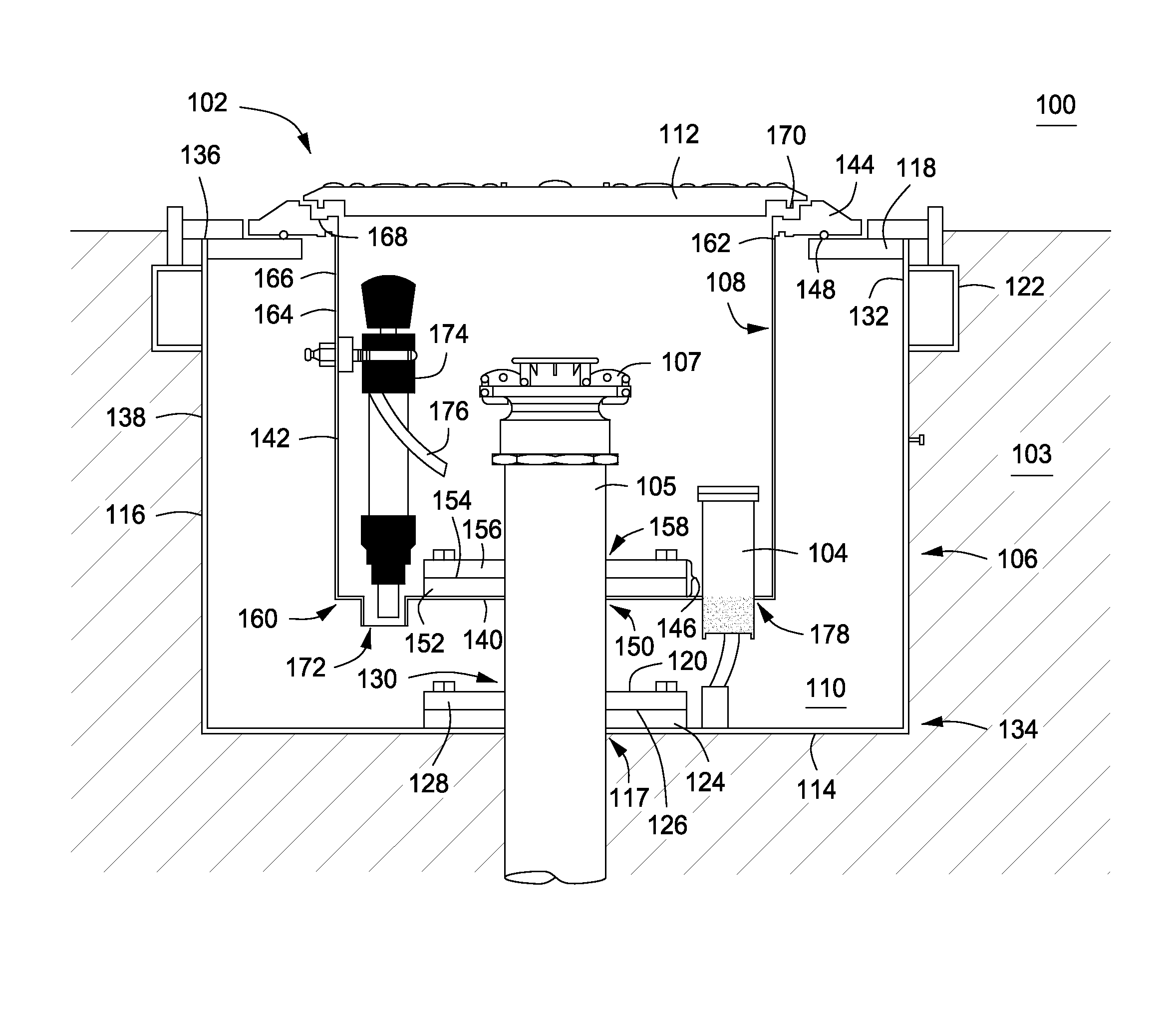
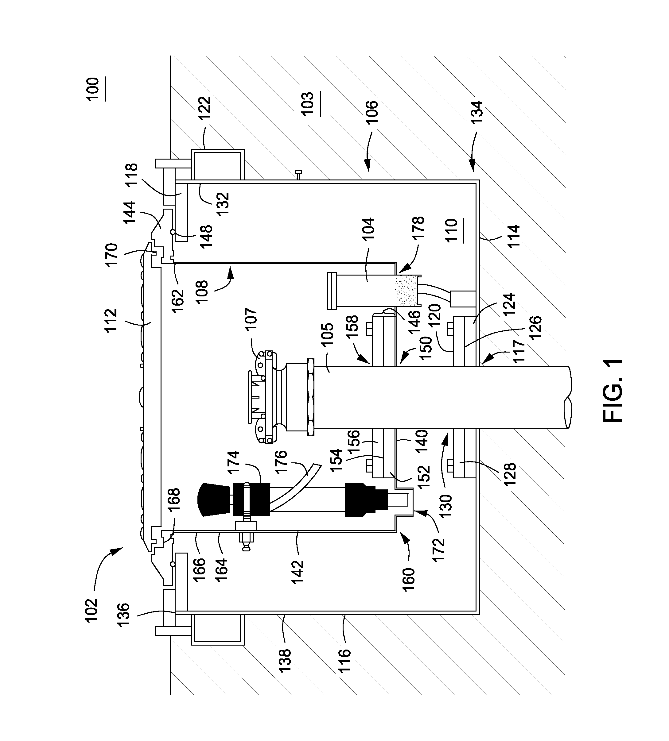
[0015]Examples described herein below generally relate to a system, apparatus and method for monitoring accumulation of fluids in a containment tank. The system and apparatus may be operable to and the method may function to prevent (i) fluids destined for an underground storage tank (“UST”) from entering into, diffusing into and / or contaminating the ground soil due to, for example, spillage or overflow of a fill pipe of the UST when filing or otherwise servicing the UST, and / or (ii) fluids present in the ground soil from entering into and / or contaminating fluids stored in the underground storage tank. The system may include a first containment chamber that defines a given volume; a second containment chamber that may be positioned substantially within the given volume; an accumulation zone defined by a volume between the first and second containment chambers; and a monitoring device for detecting accumulation of fluids in the accumulation zone.

Problems solved by technology

Unfortunately, the visual inspection and / or chemical testing of the legacy containment and double-walled containment tanks has to be performed on a periodic (e.g., daily) basis so as to ensure that the any fluids accumulated in the containers and / or the accumulation zone do not overfill and / or contaminate the ground and / or the underground storage tank.
Many times, such inspections and testing do not accurately indicate an amount and / or type of fluid accumulating.
In addition, such inspections and testing may not be performed often enough to detect a rapid accumulation of the fluids.
On the other hand, the inspections and testing may turn out to be an utter waste of resources (e.g., manpower, testing supplies, etc.) when little or no fluids accumulate in the containers and / or the accumulation zone.

Method used


Image

  • System, Apparatus and Method for Monitoring Accumulation of Fluids in a Containment Tank
  • System, Apparatus and Method for Monitoring Accumulation of Fluids in a Containment Tank
  • System, Apparatus and Method for Monitoring Accumulation of Fluids in a Containment Tank

Examples


operation example

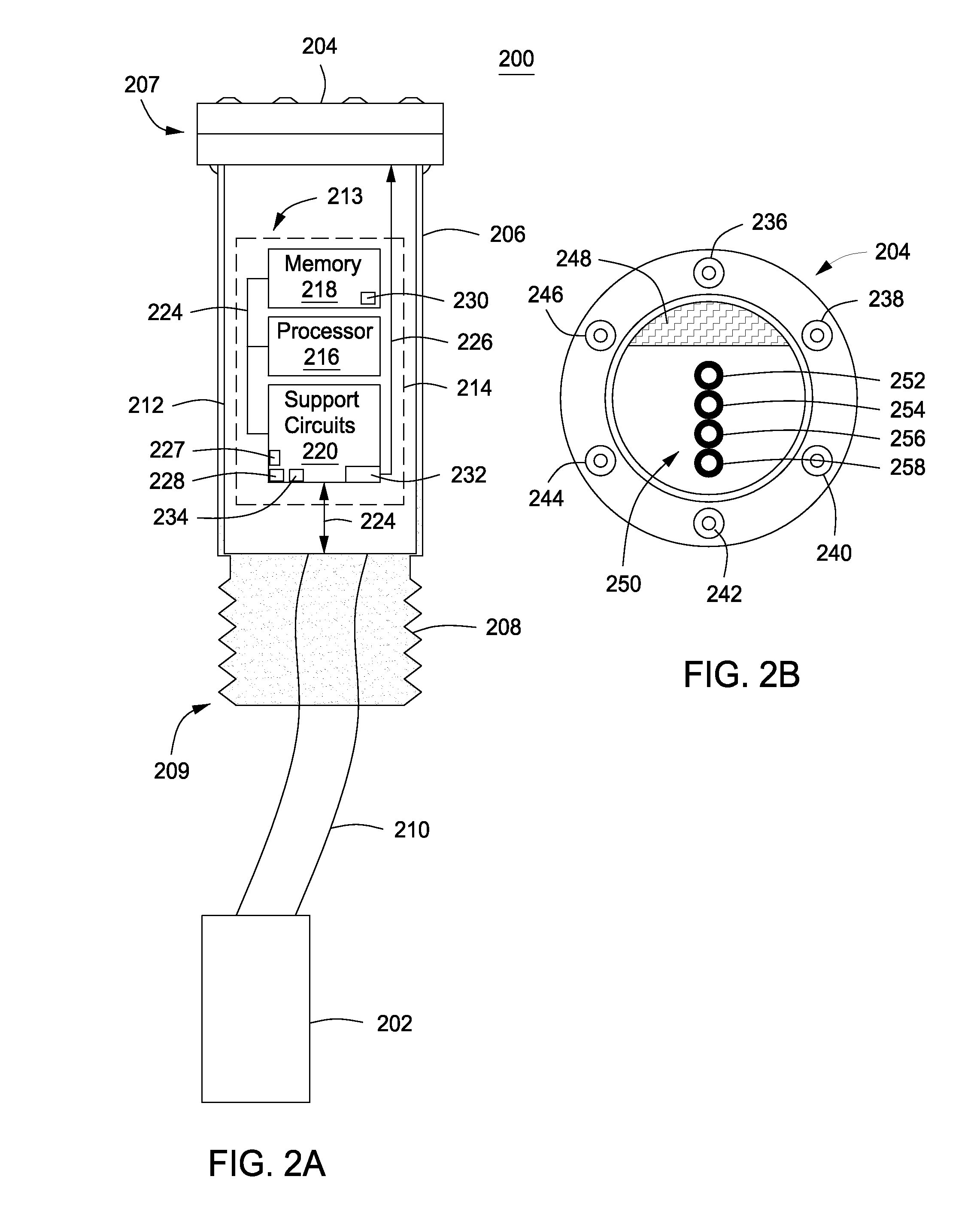
[0082]FIG. 3 is a flow chart illustrating an example of a flow 300 for detecting an accumulation of fluids that may accumulate in an accumulation zone of the containment tank. For convenience, the flow 300 is described with reference to the system 100 of FIG. 1 and the monitoring device 200 of FIG. 2. The flow 200, however, may be carried out using other architectures as well.

[0083]The flow 300 starts at termination block 310, after the monitoring device 200 is installed in containment tank 102. After termination block 310, the flow 300 transitions to process block 320.

[0084]At process block 320, the timing and / or clock circuitry 227 wakes up the processor 216 by issuing an electrical signal to the processor 216. This electrical signal may be issued on a periodic basis, and as such may indicate a predetermined amount of period (“time period”) has passed. This predetermined time period may be, for example, about 24 hours. Alternatively, the predetermined time period may ranges from b...


PUM


Abstract

A system and method for monitoring accumulation of fluids in a containment tank is provided. The system may be operable to and method may function to prevent (i) fluids destined for an underground storage tank (“UST”) from entering into, diffusing into and / or contaminating the ground soil due to, for example, spillage or overflow of a fill pipe of the UST when filing or otherwise servicing the UST, and / or (ii) fluids present in the ground soil from entering into and / or contaminating fluids stored in the underground storage tank. The system may include a first containment chamber that defines a given volume; a second containment chamber that may be positioned substantially within the given volume; an accumulation zone defined by a volume between the first and second containment chambers; and a monitoring device for detecting accumulation of fluids in the accumulation zone.

Description

BACKGROUND[0001]1. Field[0002]The following generally relates to containment tanks and monitors thereof. More particularly, the following relates to a system, apparatus and method for monitoring and / or detecting an accumulation of fluids that may accumulate in an accumulation zone of the containment tank.[0003]2. Related Art[0004]A legacy holding or containment tank, which typically resides (at least in part) in ground soil below ground level, acts a barrier between the ground soil it resides in and a subterranean fill pipe or other port of an underground storage tank. As a barrier, the legacy containment tank is operable to prevent (i) fluids destined for the underground storage tank from entering into, diffusing into and / or contaminating the ground soil due to, for example, spillage or overflow of the fill pipe when filing of the underground storage tank, and / or (ii) fluids present in the ground soil from entering into and / or contaminating fluids stored in the underground storage ...

Claims


Application Information

Patent Timeline
IPC IPC(8): B65D90/48B65D43/02B65D85/00B65D90/22
CPCB65D90/24B67D7/3209B65D90/48B65D90/26
Inventor CLOVER, DANIEL S.
Owner CLOVER DANIEL S
Learn More