Drying unit Using far Infrared Rays, Drying Apparatus Using the Unit and Waveguide for the Apparatus

a drying apparatus and infrared ray technology, applied in the field of far infrared ray drying apparatus, can solve the problems of delay in production, deterioration of painting quality, and inability to print work during cold weather, so as to improve painting quality, improve drying space, and improve energy efficiency.

Inactive Publication Date: 2009-01-08
CHO KUK RAE
View PDF73 Cites 11 Cited by
  • Summary
  • Abstract
  • Description
  • Claims
  • Application Information

AI Technical Summary

Benefits of technology

[0015]By utilizing the waveguide, the radiation distance of the far infrared rays (i.e., the electromagnetic wave energy) converted at the far infrared drying unit can be extended from 70 cm conventional up to 50 m or more. Also, by keeping the surrounding temperature of the far infrared converter at 200-500° C., the energy efficiency can be improved markedly. In this manner, the heat loss of the far infrared converter, which is the main cause of reduction in the generation rate of far infrared rays, due to the convection of heated air in the drying space, i.e., outdoors, conveyor tunnel or box-typed drying space, can be reduced very effectively.
[0016]Since the drying apparatus has a movable structure, the drying space can be used more efficiently.
[0017]In addition, the far infrared drying apparatus can improve the painting quality and further, the polishing effect. The far infrared drying apparatus of the present invention is also advantageous in that a high-quality painting can be done irrespective of weather conditions including cold weather or humid / rainy weather.
[0018]Also, the painting job and the drying process can be facilitated by moving the far infrared drying apparatus to any desired direction. Lastly, the far infrared drying unit(s) of the apparatus is well protected from a great amount of dust produced during the painting job.

Problems solved by technology

Therefore, the printing work cannot be done during cold weather, i.e., the outside temperature falling below 5° C., or during rainy weather of high humidity because the bad weather conditions often deteriorate the painting quality.
If bad weather continues for an extended period of time, the amount of painting days is automatically limited and the entire work procedure is affected thereby, causing a delay in production.
Even though the conventional large-scale drying system is usually equipped with a hot-air blowing device, its installation cost is very high and a tremendous amount of energy is required to keep the large space at high temperature.
Although the far infrared ray heating appliance was advantageous in that the drying process of painting could be done independent of weather conditions, the radiation distance of far infrared rays was as short as 0.7 m. Thus, drying a large structure such as a ship block could not be done effectively.
Also, the conventional far infrared heater had problems, for example, the heat efficiency at an electromagnetic wave converting region was often reduced due to the air convection and thus, the amount of electromagnetic radiation was rather small.

Method used


Image

  • Drying unit Using far Infrared Rays, Drying Apparatus Using the Unit and Waveguide for the Apparatus
  • Drying unit Using far Infrared Rays, Drying Apparatus Using the Unit and Waveguide for the Apparatus
  • Drying unit Using far Infrared Rays, Drying Apparatus Using the Unit and Waveguide for the Apparatus

Examples


Embodiment Construction

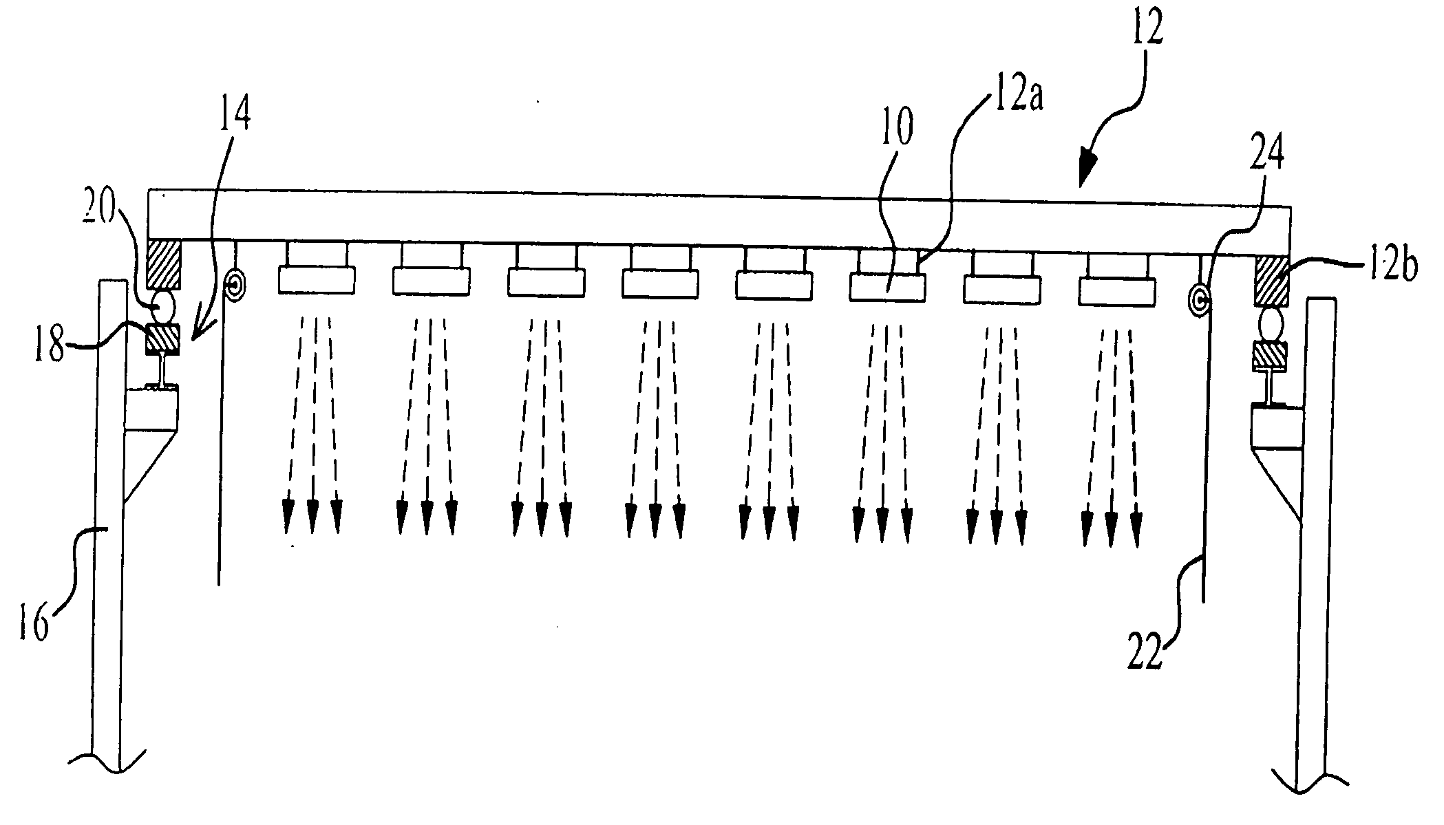
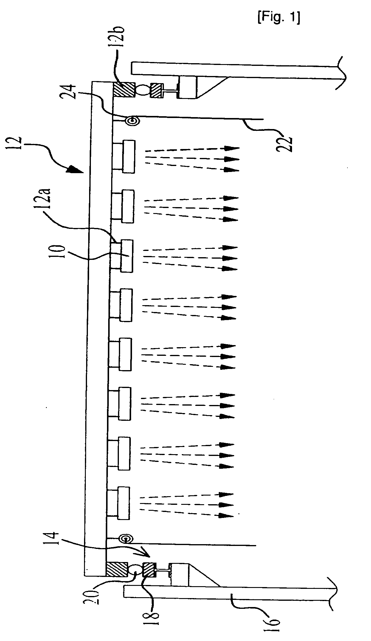
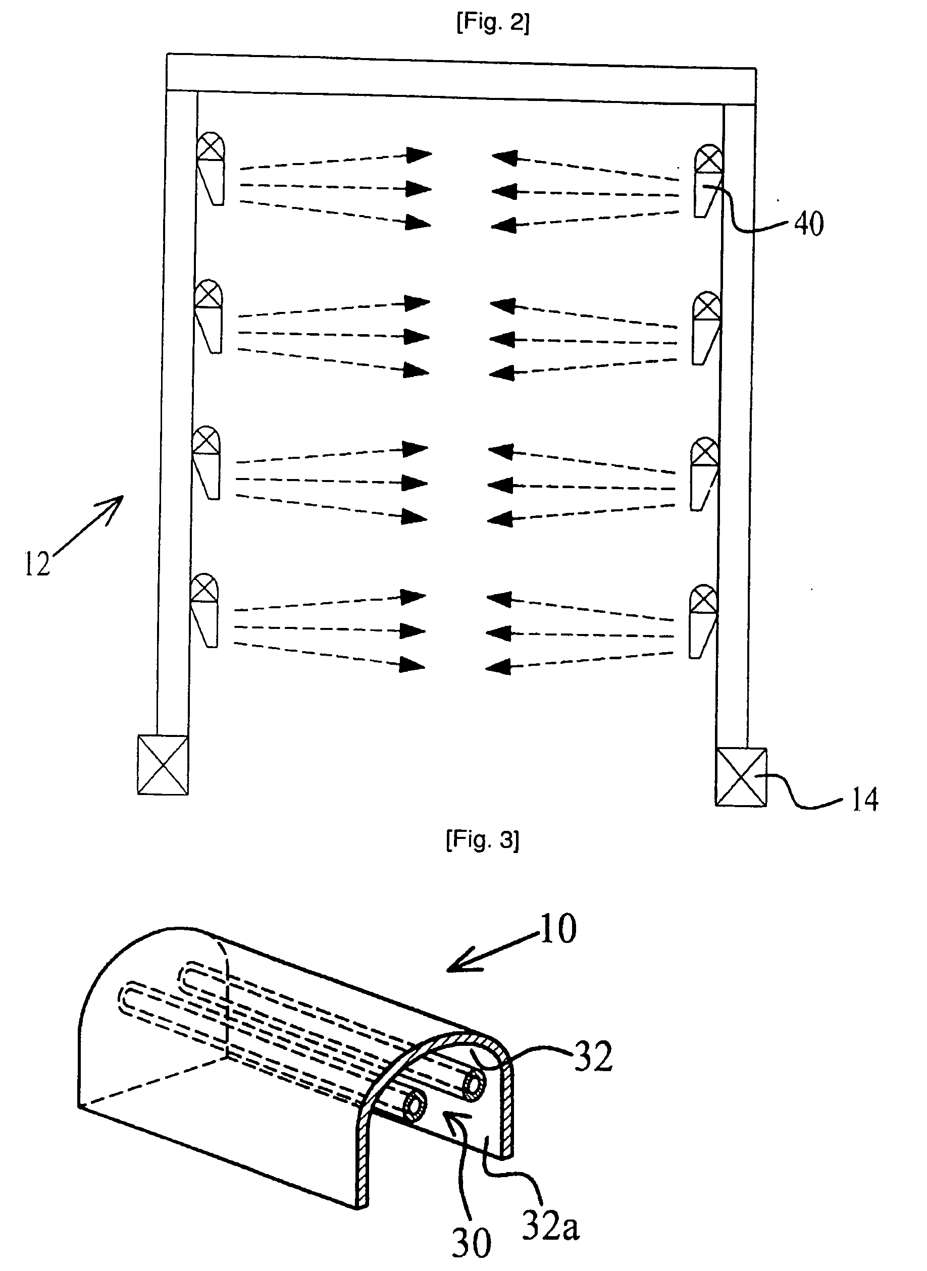
[0019]A far infrared drying apparatus of the present invention includes: a far infrared drying apparatus, including: at least one far infrared drying unit, which is heated by an electroheating element and converts heat energy into far infrared rays, namely, electromagnetic wave energy; a support frame for supporting the at least one far infrared drying unit; a moving device for moving the support frame; and a waveguide for guiding the far infrared rays over a long distance onto an object to be dried. The drying unit features a higher heating efficiency than a conventional far infrared heater, and the waveguide has extended the far infrared radiation distance from 70 cm, the maximum far infrared radiation distance of a reflective mirror used in the conventional far infrared heater, to 50 m or more. Furthermore, by preventing any loss of electromagnetic waves and guiding the far infrared rays onto a target object only, the drying efficiency was enhanced markedly.

[0020]The above and ot...


PUM


Abstract

Disclosed is a far infrared drying apparatus, including: at least one far infrared drying unit, which is heated by an electric heating element and converts heat energy into far infrared rays, namely, electromagnetic wave energy: a support name for supporting the at least one far infrared driving unit; a moving device for moving the support frame; and a waveguide for guiding the far infrared rays over a long distance onto an object to be dried.

Description

TECHNICAL FIELD[0001]The present invention relates in general to a drying apparatus using far infrared ray, and more particularly to a drying apparatus using far infrared and a drying unit using far infrared ray featuring low power consumption and improved drying efficiency, by emitting far infrared rays at high efficiency and guiding far infrared rays to an object to be dried even over a long distance. Also, the present invention relates to a foil or plate-shaped waveguide for far infrared guidance, which is made of vacuum-deposited metal fiber or fiber with a thin metal plate being attached to one side or both sides thereof.BACKGROUND ART[0002]In general, ship block, marine structures, and other large steel structures are painted a lot to maintain their performance and durability. In fact, the quality of the painting is very important because it is directly related to the lifespan of a ship or a structure. Drying process of the paint is much important as a determining factor of th...

Claims


Application Information

Patent Timeline
Patent Type & Authority Applications(United States)
IPC IPC(8): F26B3/34F26B3/30
CPCF26B3/30
Inventor CHO, KUK RAE
Owner CHO KUK RAE
Why Eureka
Try Eureka