Mechanical Press Drive System and Method

a drive system and mechanical press technology, applied in memory systems, forging hammers, program control, etc., can solve the problems of affecting the quality of pressing, requiring a great deal requiring a large amount of skill and knowledge, so as to reduce the peak power requirement of the drive motor, reduce the overall production cycle time without compromising pressing quality, and increase the opportunity for optimizing the press line

Active Publication Date: 2009-01-08
ABB (SCHWEIZ) AG
View PDF24 Cites 23 Cited by
  • Summary
  • Abstract
  • Description
  • Claims
  • Application Information

AI Technical Summary

Benefits of technology

[0035]The principal advantage of the improved press is that the motor speed may be variably controlled during a production cycle. This allows a degree of control and operational accuracy that is not available in todays mechanical presses such as flywheel presses. The advantage gained is that the total time for a production cycle with the improved press may be reduced compared to a production cycle time for an equivalent mechanical, flywheel-type press.
[0050]In production settings where more than one press works in a same or related production process, such as a line of presses, the inventive press provides greater opportunity for optimization of a press line by coordinating the motion of all presses and feeders or transfer mechanisms / unloaders such as loading / unloading robots, in the process or press line. Coordination between presses and / or presses and loaders / unloaders may be achieved by, for example, controlling such a line using a single controller, which is enabled due to the improved controllability of the presses according to one or more embodiments of the invention. Coordination or optimisation may be achieved in part by adapting speed during opening / closing a press (while for example maintaining a required speed and energy output during the pressing / stamping part of the cycle), resulting in a press motion which may be optimised dependent on parameters such as: a state of a downstream process; or a state of an upstream process or another consideration such as overall power or energy consumption; smoothing power consumption peaks in the press line.

Problems solved by technology

When a die or mould of such presses is to be changed, the setup involving setting the mechanical positions to compensate for wear over time etc. is usually a complicated and lengthy process including mechanical adjustments that require a great deal of skill and knowledge.
A press with this type of transmission generally has a high peak power requirement.
However, the device shown has a ball-screw drive which type of transmission up till now has usually been limited in the amount of force that may be transmitted and limited by cost of manufacture to small presses and / or for stamped products of high value.
However, servo motor presses may have a high peak power consumption for some products, especially large products requiring deep drawing.

Method used


Image

  • Mechanical Press Drive System and Method
  • Mechanical Press Drive System and Method
  • Mechanical Press Drive System and Method

Examples


Embodiment Construction

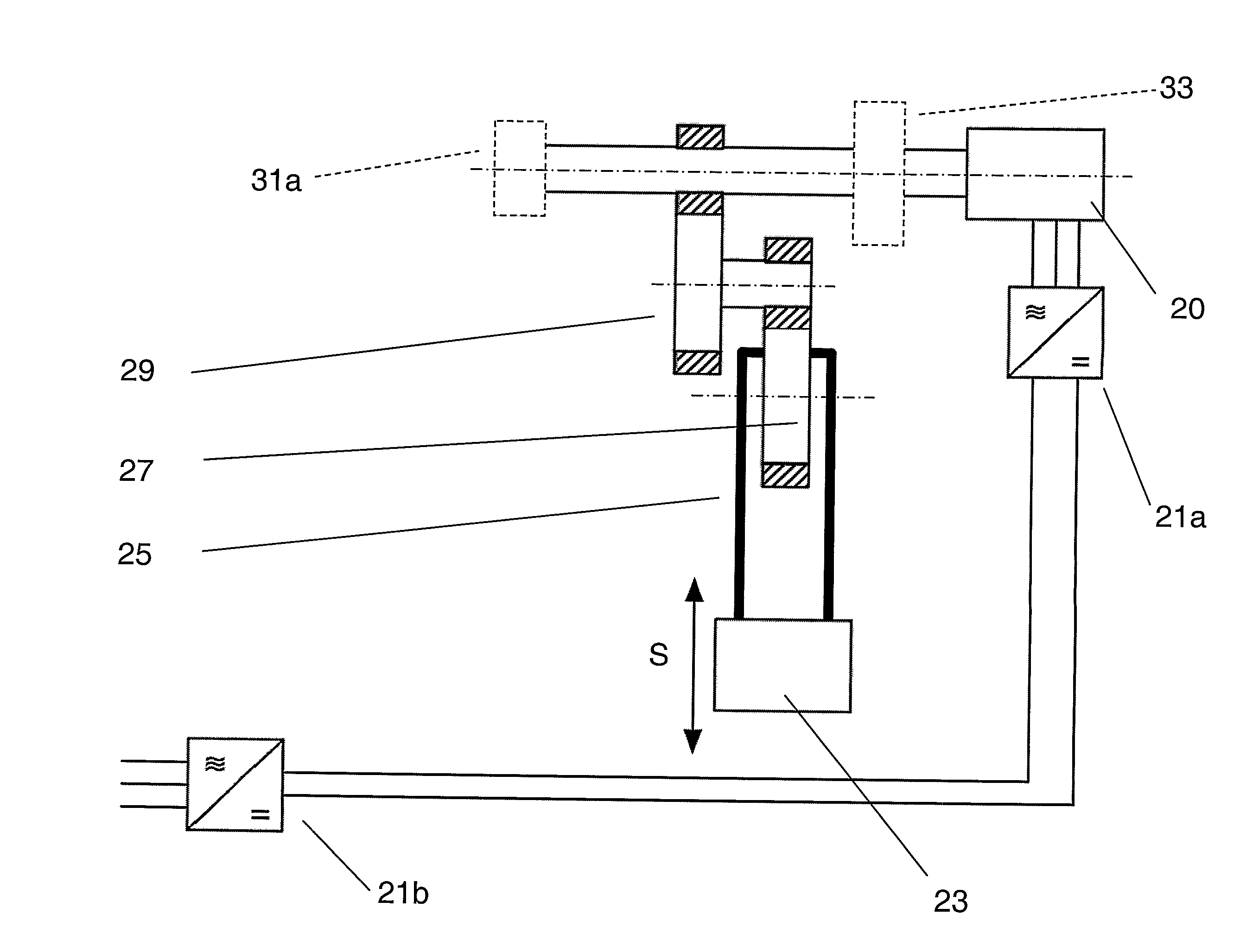
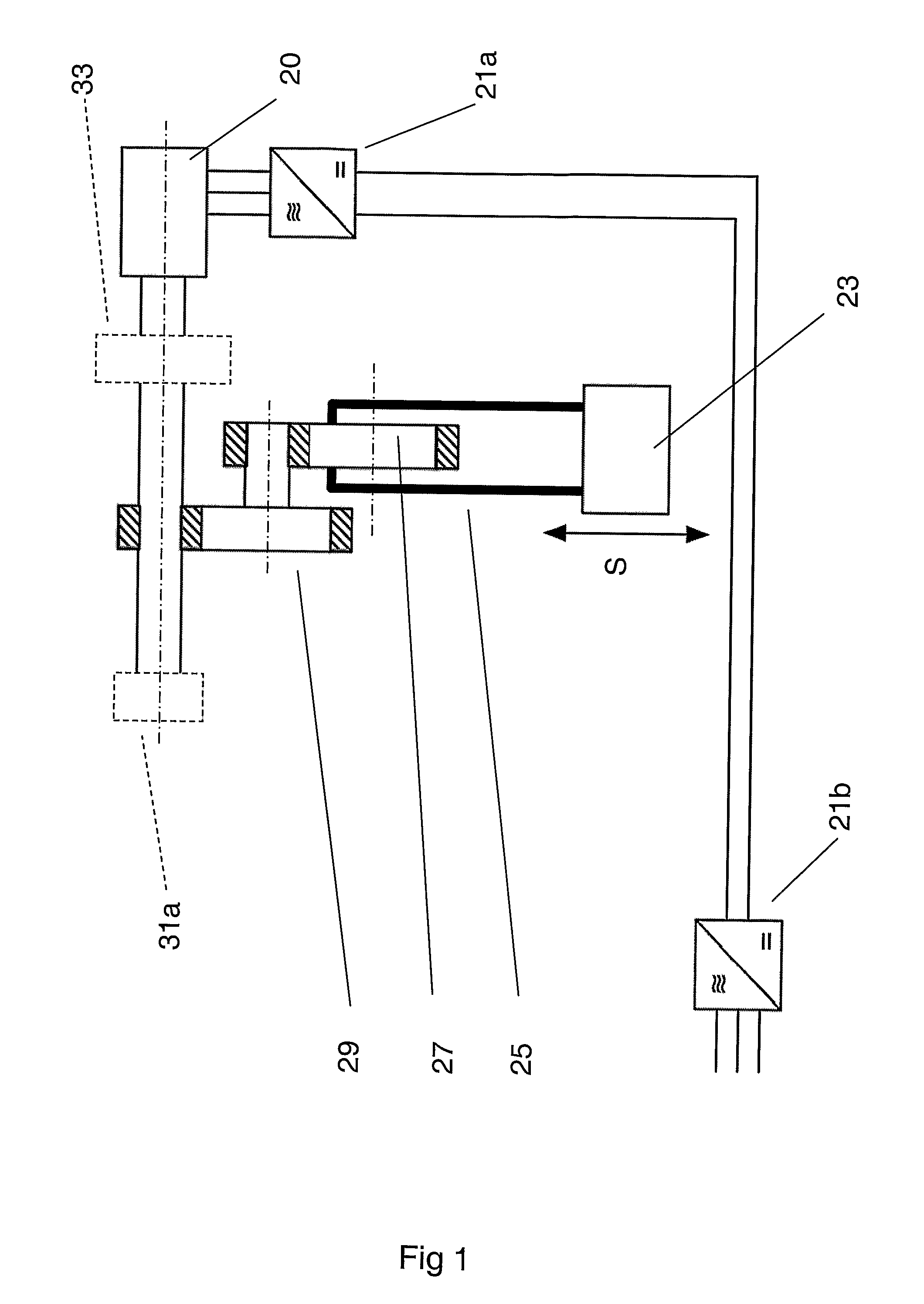
[0064]FIG. 1 shows a schematic layout for an improved mechanical press according to an embodiment of the invention. It shows in a simplified way a press ram 23, an eccentric drive wheel 27, a press gear mechanism 29, and an electric drive motor 20. It also shows motor power supply and control means 21a and 21b. The figure shows press ram 23 which is driven in a up-and-down motion S by an eccentric drive wheel 27 or crank and a link 25. The eccentric drive wheel is in turn driven by a press gear mechanism 29 which is shown in a simplified cross section in which gear teeth are indicated by cross-hatching. The eccentric wheel is driven through the press gear mechanism by the drive motor 20. Drive motor 20, which may be a servo motor, is arranged with an inverter 21a and a rectifier 21b which are connected to a grid or power network (not shown). Other motor control means may be substituted. The Figure also shows an optional emergency brake 31a and an optional gearbox 33, either of which...


PUM

PropertyMeasurementUnit
crank angleaaaaaaaaaa
rotationaaaaaaaaaa
crank angle rotationaaaaaaaaaa

Abstract

A method for operating a mechanical press including at least one electric drive motor, a drive control for controlling the at least one motor, a ram, a mechanical element for translating rotational motion of the at least one motor to linear motion of the ram in a first rotation direction, into a linear motion of the ram arranged to be lowered and raised along a linear path for operating the press to carry out a press cycle including a pressing part and one or more non-pressing parts of the press cycle, and by providing a control output to the drive control such that the speed of the at least one drive motor is varied during at least one pressing or non-pressing part of the press cycle. The press may be reversed between production cycles. Also press and system including a such press.

Description

TECHNICAL FIELD[0001]The invention concerns a mechanical press of the type used for pressings, stamping or punching of metal parts from blanks. In particular, the invention discloses a mechanical press driven by an electric motor with an improved system controlling transmission of power from the drive motor to the ram of the press.TECHNICAL BACKGROUND[0002]Mechanical presses are commonly used to produce stamped car parts from steel blanks or workpieces. Traditionally the press drive and power transmission system, or kinematics is driven via a flywheel. The function of the flywheel is to store the necessary energy to make a cycle. The flywheel is connected and disconnected to the kinematics by means of a clutch and brake system (which may be pneumatic or hydraulic). When a die or mould of such presses is to be changed, the setup involving setting the mechanical positions to compensate for wear over time etc. is usually a complicated and lengthy process including mechanical adjustment...

Claims


Application Information

Patent Timeline
Patent Type & Authority Applications(United States)
IPC IPC(8): B21J7/46B28B5/00G06F9/44
CPCB30B15/148B30B1/266B21D43/02B30B15/14B30B15/146G05B19/41815G05B2219/39105G05B2219/45142Y02P80/10Y02P90/02G05B19/418
Inventor SEGURA GOLORONS, MARCBOSGA, SJOERD
Owner ABB (SCHWEIZ) AG
Why Eureka
Try Eureka